
Fluid feeding pump, medical apparatus, and air bubble detection method for fluid feeding pump

a technology of fluid feeding pump and medical equipment, which is applied in the direction of pump control, fluid jet surgical cutter, positive displacement liquid engine, etc., can solve the problems of inability to feed fluid, increased size of circulation pump, and inability to provide separate devices for detecting air bubbles

Active Publication Date: 2013-02-28
SEIKO EPSON CORP
View PDF11 Cites 9 Cited by
  • Summary
  • Abstract
  • Description
  • Claims
  • Application Information

AI Technical Summary

Benefits of technology

The technology in this patent enables the detection of air bubbles in a pump chamber without increasing the size of the device. By measuring the small voltage change of the drive signal, the current flowing through the piezoelectric element can be accurately detected, and whether there are air bubbles or not can be determined accurately. The analysis of the frequency components of the current waveform also allows for easy detection of air bubbles.

Problems solved by technology

Therefore, the fluid cannot be fed.
However, the above technique has a problem that the circulation pump is increased in size because the detection device for detecting air bubbles needs to be provided separately in the circulation pump.
Therefore, a separate device for detecting air bubbles need not be provided in the fluid feeding pump.
Also, in such a determination of whether there are air bubbles or not, a separate device for detecting air bubbles need not be provided in the fluid feeding pump.

Method used


Image

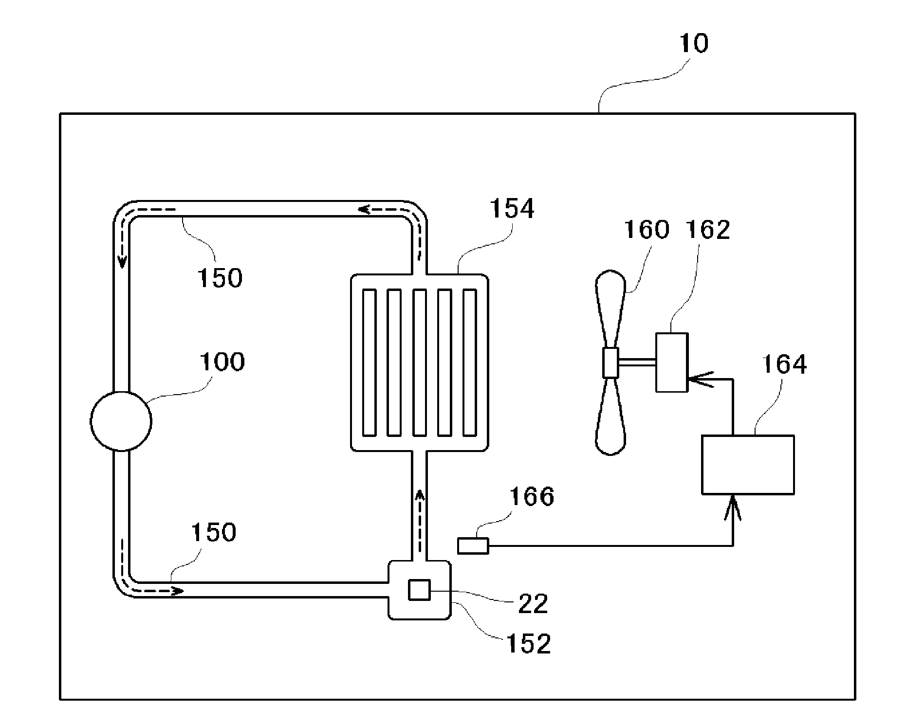
  • Fluid feeding pump, medical apparatus, and air bubble detection method for fluid feeding pump
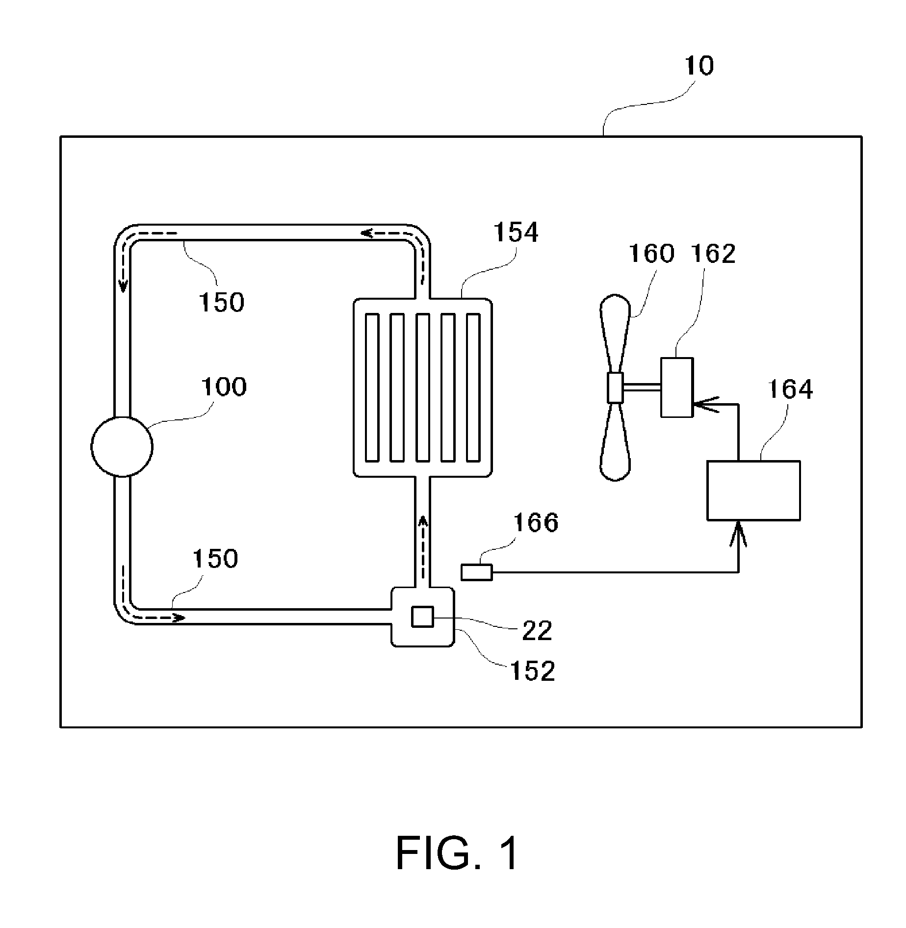
  • Fluid feeding pump, medical apparatus, and air bubble detection method for fluid feeding pump
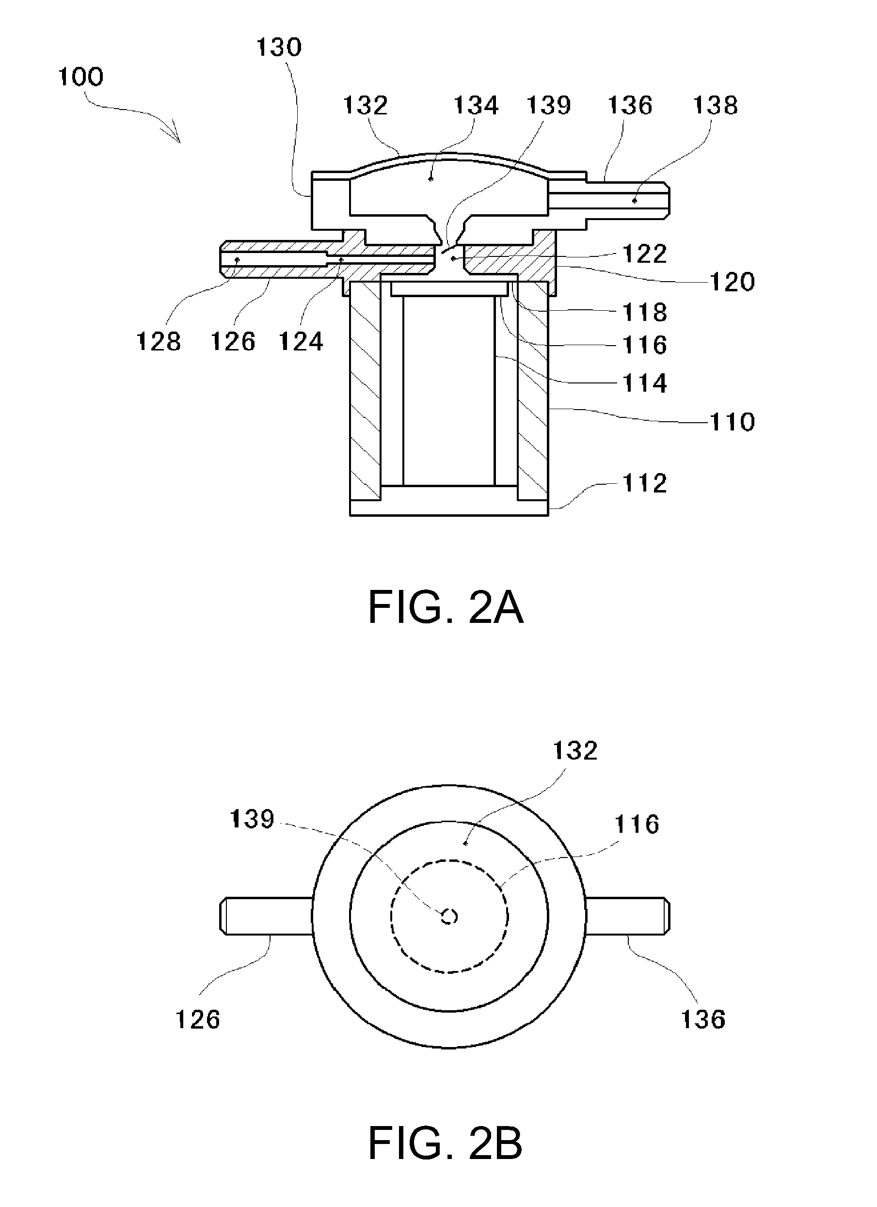
  • Fluid feeding pump, medical apparatus, and air bubble detection method for fluid feeding pump

Examples


first example

E. First Example

[0061]FIG. 5 is an explanatory view showing the inner configuration of the air bubble detecting unit 220 according to a first example. As shown in FIG. 5, the air bubble detecting unit 220 of the first example is configured with electric circuits including a switch unit 222, a switch control unit 224, a current detecting unit 226, a comparator unit 228 and the like.

[0062]The piezoelectric element 114 of the fluid feeding pump 100 is connected to the switch unit 222 of the air bubble detecting unit 220. The switch unit 222 is formed mainly by an analog switch and the switch changes over between ON and OFF under the control of the switch control unit 224. In the switch unit 222, the switch is usually ON in response to a Hi-state control signal from the switch control unit 224. Therefore, the piezoelectric element 114 and the current detecting unit 226 are connected with each other. Meanwhile, as a trigger signal from the drive signal generating unit 210 is inputted to ...

second example

F. Second Example

[0074]The above-described air bubble detecting unit 220 of the first example is described as detecting whether there is a current flowing through the piezoelectric element 114 or not after the application of the maximum voltage in order to detect a change of the drive current waveform in the piezoelectric element 114 after the drive signal reaches the maximum voltage. Here, to detect a change of the drive current waveform, the amplitude of a specific frequency component of the drive current waveform may be detected.

[0075]FIG. 7 is an explanatory view showing the result of a spectral analysis of the drive current waveform when the drive signal is applied to the piezoelectric element 114. In FIG. 7, a solid line shows the result of the spectral analysis of the drive current waveform in the case where there are no air bubbles in the pump chamber 122, and a broken line shows the result of the analysis in the case where there are air bubbles.

[0076]As shown in FIG. 7, com...


PUM


Abstract

A fluid feeding pump which varies a volume of a pump chamber and thus feeds a fluid out of the pump chamber, includes: a piezoelectric element which accumulates electric charges inside when a voltage is applied, and which deforms according to an amount of accumulated electric charges and thus increases or decreases the volume of the pump chamber; a drive unit which applies a drive signal with a waveform increasing to a predetermined maximum voltage and then decreasing, and thus drives the piezoelectric element; and an air bubble determining unit which detects a current flowing through the piezoelectric element within a predetermined period after the drive signal is applied to the piezoelectric element, and thus determines whether there are air bubbles in the pump chamber or not.

Description

BACKGROUND[0001]1. Technical Field[0002]The present invention relates to a fluid feeding pump which feeds a fluid.[0003]2. Related Art[0004]A circulation pump which circulates a fluid through a channel is previously known. The circulation pump has a pump chamber with a variable volume. After the volume of the pump chamber is increased to suck a fluid into the pump chamber from the channel, the volume of the pump chamber is reduced to pressurize the fluid in the pump chamber. The fluid is thus fed into the channel from the pump chamber. Therefore, by increasing and decreasing the volume of the pump chamber, the fluid can be circulated through the channel.[0005]In the case where air bubbles enter the pump chamber, when the volume of the pump chamber is reduced, the air bubbles are compressed and fluid is not pressurized. Therefore, the fluid cannot be fed. Thus, a technique of providing the circulation pump with a detection device for detecting air bubbles in the pump chamber and carr...

Claims


Application Information

Patent Timeline
IPC IPC(8): F04B45/047
CPCF04B13/02F04B17/03F04B43/046A61B17/3203F04B45/047
Inventor MATSUZAKI, TAKAHIROSETO, TAKESHITABATA, KUNIOMIYAZAKI, SHINICHI
Owner SEIKO EPSON CORP
Learn More