Real-Time Calculation of Total Longitudinal Force and Aerodynamic Drag Acting on a Rider on a Vehicle

a technology of total longitudinal force and aerodynamic drag, which is applied in the measurement of vehicle tractive/propulsive power, instruments, force/torque/work measurement, etc., and can solve the problems of limited effect and not directly measured

Active Publication Date: 2013-02-28
BODY ROCKET LTD
View PDF2 Cites 22 Cited by
  • Summary
  • Abstract
  • Description
  • Claims
  • Application Information

AI Technical Summary

Problems solved by technology

For vehicles with an exposed rider, the effectiveness of this method is limited because of the dynamic nature of a person's posture.
However, forces are not directly measured and the teaching of this document does not address th

Method used


Image

  • Real-Time Calculation of Total Longitudinal Force and Aerodynamic Drag Acting on a Rider on a Vehicle
  • Real-Time Calculation of Total Longitudinal Force and Aerodynamic Drag Acting on a Rider on a Vehicle
  • Real-Time Calculation of Total Longitudinal Force and Aerodynamic Drag Acting on a Rider on a Vehicle

Examples


Embodiment Construction

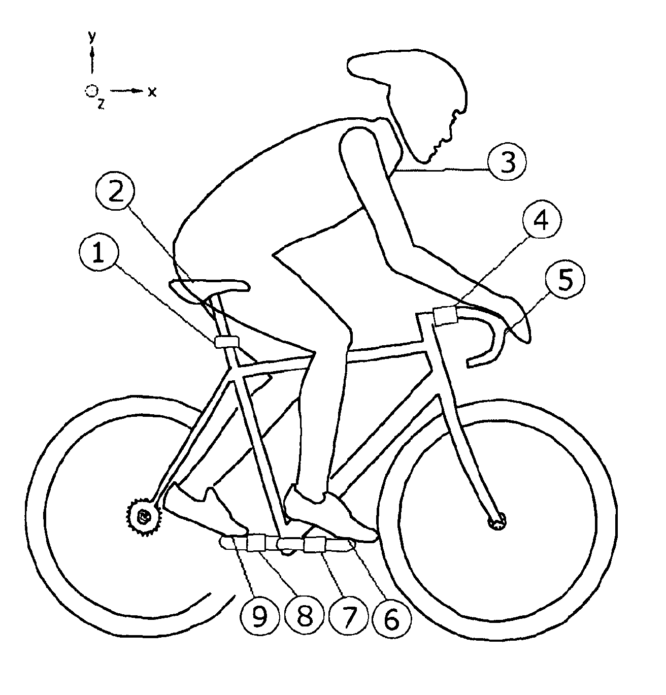
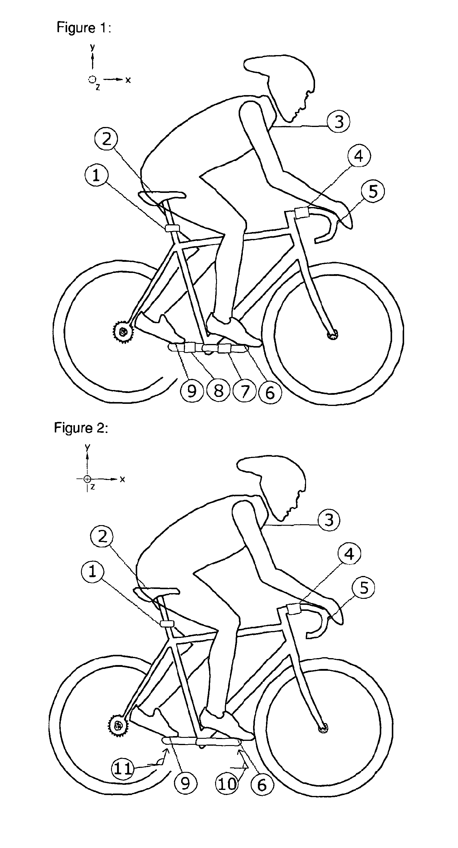
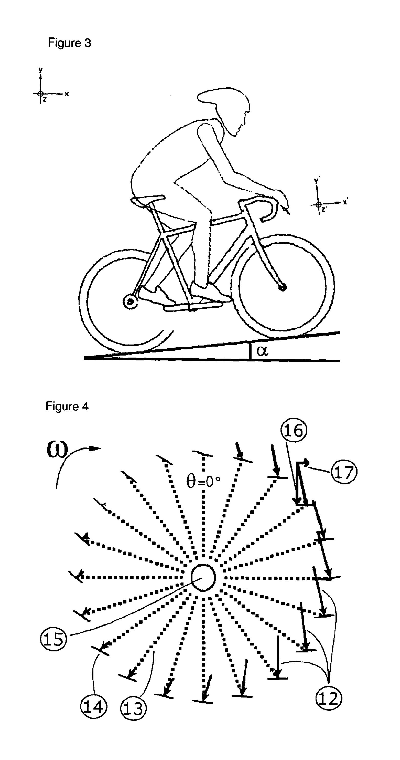
[0041]This invention aims to disclose a system and methods of continuous aerodynamic drag monitoring of an exposed rider on a vehicle. The basic theory of physics behind this invention is that when a vehicle that exposes a rider travels through the air, drag forces exert a rearward force on the rider. The vehicle exerts an equal but opposite force on the rider to propel the body through the air. This force must be transferred to the rider through the body's limited points of contact with the vehicle. At least one force sensor is located at or near the one or more points of contact between the rider and the vehicle to measure a force of the vehicle on the rider. The measured force from the or each force sensor can then be processed to determine aerodynamic drag acting on the rider on the vehicle.

[0042]In the following description, and for the purposes of explanation, numerous specific details are set forth in order to provide a thorough understanding of the various aspects of the inv...


PUM


Abstract

A system and method of calculating under changing conditions in real-time aerodynamic drag acting on a rider on a vehicle. A computer receives a signal indicative of a force of the vehicle on the rider from at least one force sensor located at or near at least one point of contact between the rider and the vehicle. The computer determines aerodynamic drag acting on the rider on the vehicle from the received signal. These steps are repeated under changing conditions.

Description

FIELD OF THE INVENTION[0001]The Invention generally relates to the calculation under changing conditions in real-time of aerodynamic drag acting on a rider on a vehicle.DESCRIPTION OF RELATED ART[0002]As to reduce the complexity and length of the Detailed Specification, and to fully establish the state of the art in certain areas of technology, Applicant herein expressly incorporates by reference all of the following materials identified below:[0003]DE3612599—Method for determining the aerodynamic forces acting on a vehicle;[0004]US20080257068 (A1)—Wheel, test stand and method for determining aerodynamic characteristics of a test vehicle;[0005]U.S. Pat. No. 7,377,180 (B2)—Method for measuring total force in opposition to a moving vehicle;[0006]RU2129260—Method and device determining force of air head resistance to vehicle;[0007]JP6201713—Wind speed measuring device;[0008]NL1010278—Wind resistance meter for bicycle is mounted on handlebars and uses hinged wind vane linked to spirit l...

Claims


Application Information

Patent Timeline
IPC IPC(8): G01L1/00G06F19/00
CPCG01L1/247G01M9/06G01L5/13
Inventor DEGOLIER, ERIC
Owner BODY ROCKET LTD
Why Eureka
Try Eureka