Link actuation device

a technology of actuating device and link, which is applied in the direction of rotary shaft, program-controlled manipulator, joint, etc., can solve the problems of large volume of device in its entirety, increased difficulty in manipulating precisely, and increased difficulty in handling device. , to achieve the effect of large range of movemen

Active Publication Date: 2013-03-07
NTN CORP
View PDF8 Cites 24 Cited by
  • Summary
  • Abstract
  • Description
  • Claims
  • Application Information

AI Technical Summary

Benefits of technology

[0008]In view of the foregoing, the present invention is intended to address to the provision of a link actuating device that is structured as a two-degree-of-freedom mechanism...

Problems solved by technology

As a result thereof, the device in its entirety tends to become bulky.
The larger the device is in size, the more difficult it is to han...

Method used


Image

  • Link actuation device
  • Link actuation device
  • Link actuation device

Examples


Embodiment Construction

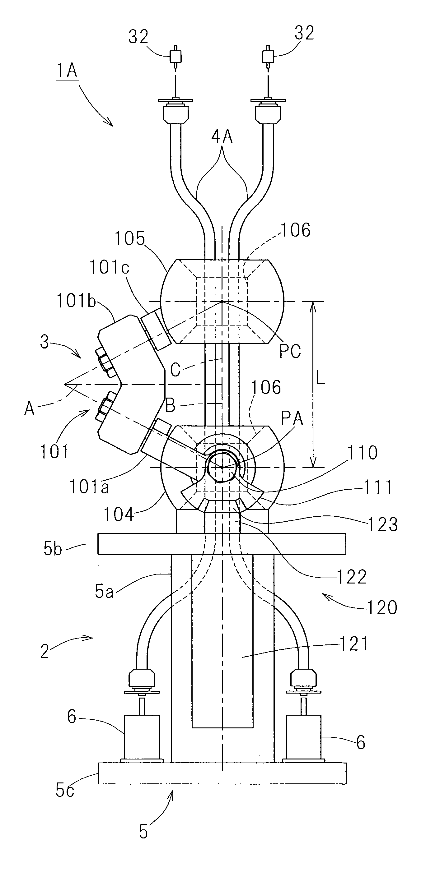
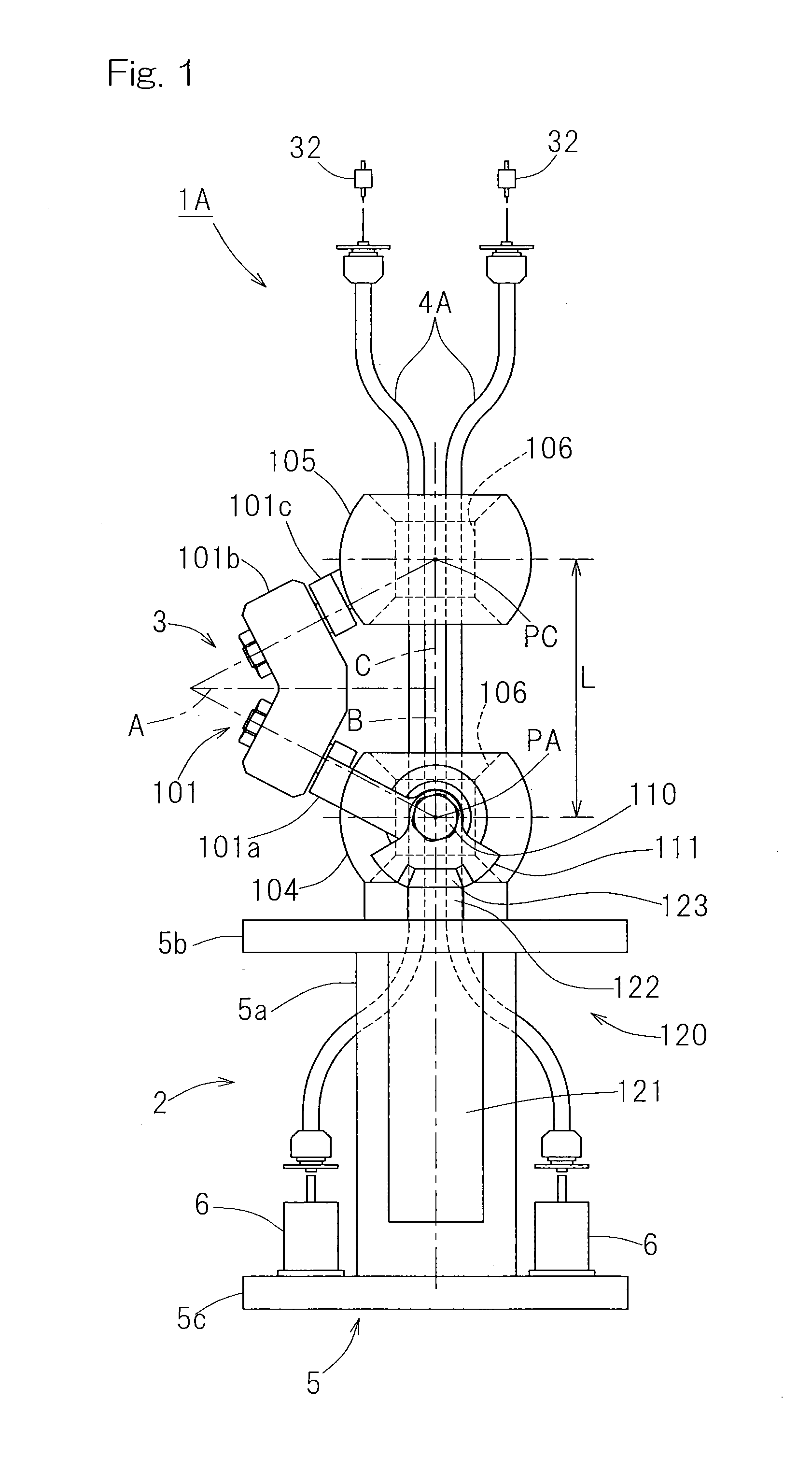
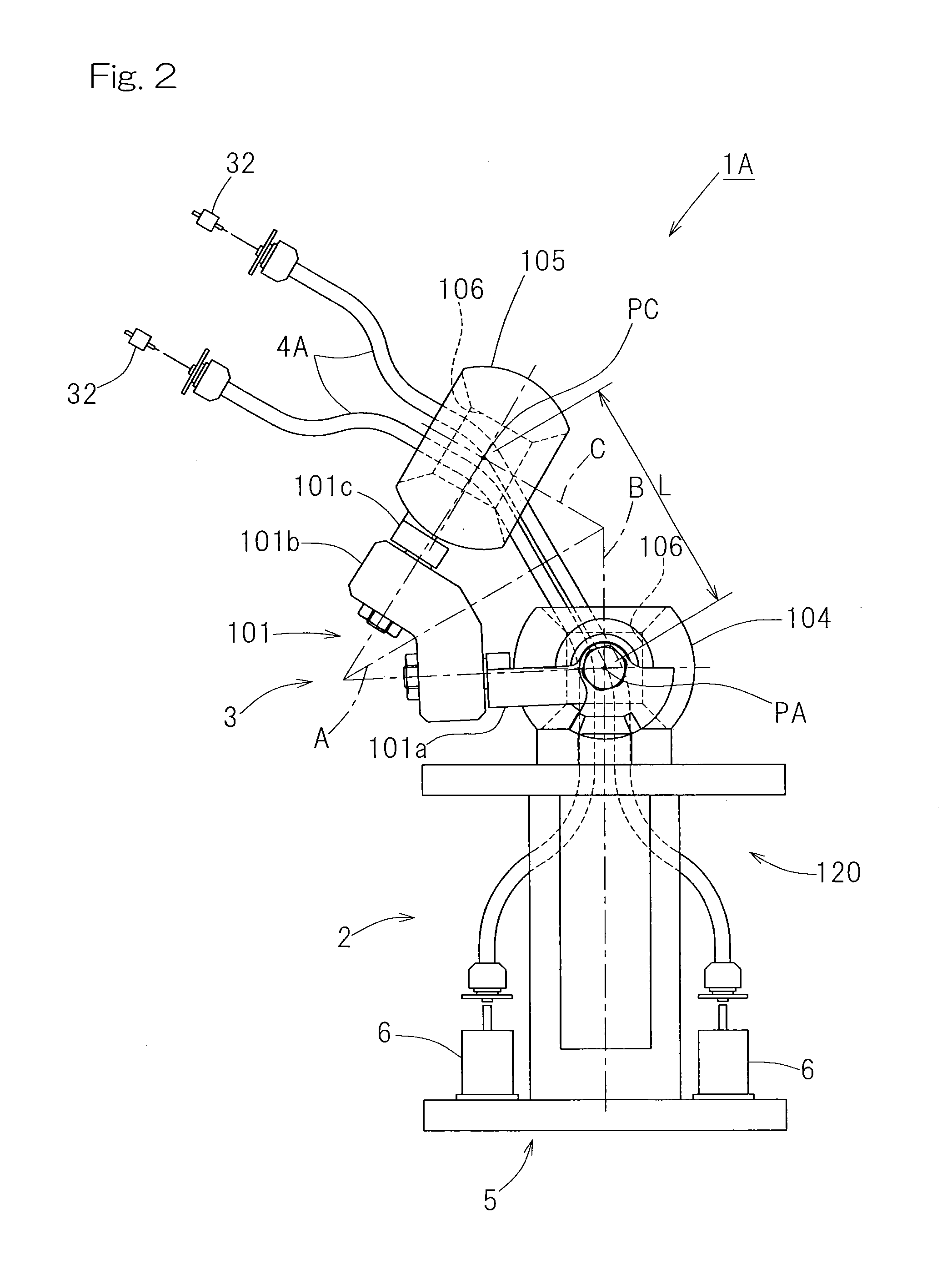
[0055]A first preferred embodiment of the present invention will be described in detail with particular reference to FIG. 1 to FIGS. 5A to 5C. As shown in FIGS. 1 and 2, a link actuating device, generally identified by 1A, includes a drive section 2 forming a base of the device, a link mechanism section 3 having an input side supported by the drive section 2, and a flexible wire 4A provided through inside of the link mechanism section 3 for transmitting a rotational force therethrough. The link mechanism section 3 also has an output side on which a driven device (not shown) such as, for example, a processing equipment is mounted, and this drive mechanism becomes a movable portion movable relative to the drive section 2. In the illustrated embodiment, the flexible wire 4A is employed in two in number, but the number of the flexible wire 4A may not necessarily be limited to that shown provided that one or more flexible wires are employed. It is to be noted that in FIGS. 1 and 2, diffe...


PUM


Abstract

An output member is connected with an input member through three sets of link mechanisms for alteration in attitude. The link mechanism includes end portion link mechanisms on an input side and an output side, respectively, and an intermediate link member. The link mechanism is such that a geometric model of each of the link members expressed by lines represents such a shape as an input side portion and an output side portion relative to a center of the intermediate link member are symmetrical with each other. By actuating two or more sets of the link mechanisms by means of a link mechanism drive source, the attitude of the output member is controlled. Through the inside of an arrangement of the link mechanisms, a flexible wire is provided for transmitting a rotational force in a direction of arrangement of the input and output members.

Description

CROSS REFERENCE TO THE RELATED APPLICATION[0001]This application is based on and claims Convention priority to Japanese patent application No. 2010-115095, filed May 19, 2010, the entire disclosure of which is herein incorporated by reference as a part of this application.BACKGROUND OF THE INVENTION[0002]1. Field of the Invention[0003]The present invention relates to a link actuating device that may be used in a link mechanism such as, for example, a parallel link mechanism or a robot articulated joint which executes a work such as a complicated processing or article handling in a three dimensional space at high speed and with precision.[0004]2. Description of Related Art[0005]One example of processing machines utilizing a parallel link mechanism is disclosed in the patent document 1 listed below. The processing machine disclosed therein is of a type in which the movement and the change in posture of a movable part are effected by means of the parallel link mechanism, and the movabl...

Claims


Application Information

Patent Timeline
IPC IPC(8): B25J18/06
CPCF16C1/02F16D1/04Y10T74/20323B25J9/104B25J9/0048
Inventor ISOBE, HIROSHIOZAKI, TAKAYOSHI
Owner NTN CORP
Why Eureka
Try Eureka