
Method for forming an isolation trench

a technology of isolation trenches and trenches, applied in the field of microelectronics, can solve the problems of reducing the probability of forming voids deep inside the trench, increasing so as to reduce the probability of forming voids in the trench

Inactive Publication Date: 2013-03-07
STMICROELECTRONICS (CROLLES 2) SAS
View PDF4 Cites 0 Cited by
  • Summary
  • Abstract
  • Description
  • Claims
  • Application Information

AI Technical Summary

Benefits of technology

This patent relates to a method for making isolated trenches in semiconductor devices, specifically, a method that reduces the likelihood of voids forming in the trenches, especially in the upper portion. The method utilizes chemical-mechanical polishing to create a smooth profile in the trenches, which promotes the deposition of dielectric material without any voids. This results in a smoother slope in the upper portions of the trenches, improving the overall quality of the semiconductor device.

Problems solved by technology

However, such a deposition may induce the forming of voids in the trench during the filling.
Indeed, with the conformal deposition techniques used to fill this cavity, one can observe that the more abrupt the wall, the higher the probability for voids to form in the trench.
Such techniques decrease the probability of forming of voids deep inside the trench, but increase the probability of forming of voids at the trench surface.
Thereby, with such thin trench filling techniques, the voids tend to form more at the trench surface than in depth.

Method used


Image

  • Method for forming an isolation trench
  • Method for forming an isolation trench

Examples


Embodiment Construction

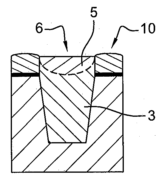
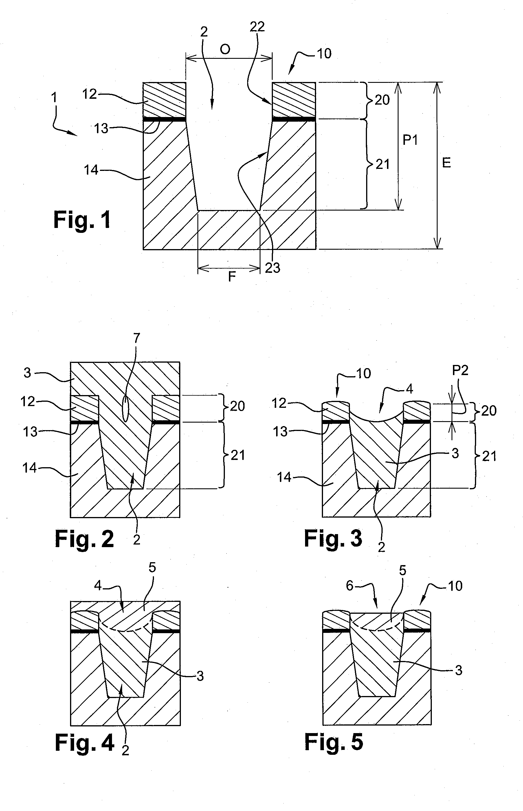
[0029]The method for forming an isolation trench in a substrate especially comprises digging into an upper portion a first cavity totally filled with a dielectric material, to remove the possible voids present in this upper portion. The second cavity thus formed preferably has a geometry capable of limiting, or even eliminating, the occurrence of voids on deposition of another dielectric material in this second cavity. FIGS. 1 to 5 illustrate the steps of the method for forming such an isolation trench in a substrate 1 having an upper surface 10.

[0030]This method first comprises:

[0031]the forming (FIG. 1), across the thickness E of substrate 1, of a first cavity 2 opened towards upper surface 10; and

[0032]the total filling (FIG. 2) of first cavity 2 with a first dielectric material 3.

[0033]Preferably, first cavity 2 has a geometry suitable for a conformal deposition of the first dielectric material 3 without the forming of voids in a lower portion 21 of this first cavity 2 and with ...


PUM


Abstract

A method forms at least one isolation trench in a substrate having an upper surface. The method includes at least: forming, across the substrate thickness, at least one first cavity opened towards the upper surface; totally filling this first cavity with a dielectric material of a first type; forming a second cavity in an upper portion of the first cavity thus filled, said second cavity being opened towards the upper surface and having a substantially concave profile; totally filling this second cavity with a dielectric material of a second type; and leveling the free surface of the trench substantially down to the upper surface level.

Description

BACKGROUND[0001]1. Technical Field[0002]The present disclosure relates to microelectronics. It more specifically relates to an improvement relative to isolation trenches, such as commonly called STI (Shallow Trench Isolation) by those skilled in the art.[0003]2. Description of the Related Art[0004]Generally, active areas are currently provided in a substrate for component or electric circuit forming purposes. Further, to electrically isolate an active area from another neighboring active area, isolation areas of isolation trench type are also currently formed in this substrate.[0005]Such trenches generally are cavities etched into the substrate and filled with a dielectric material, such as a material made of oxide, for example, silicon dioxide. A polishing then enables to remove the excess dielectric material and to level the surface of the structure.[0006]In practice, the trench is generally filled by conformal deposition, that is, with a substantially constant thickness whatever ...

Claims


Application Information

Patent Timeline
Patent Type & Authority Applications(United States)
IPC IPC(8): H01L29/06H01L21/762
CPCH01L21/76224
Inventor FAVENNEC, LAURENTPERROT, CEDRIC
Owner STMICROELECTRONICS (CROLLES 2) SAS
Learn More