Rear attachment unit for a motor vehicle

a technology for rear attachment and motor vehicles, which is applied in the direction of vehicle components, towing devices, and understructures, etc., can solve the problems of invariable doubling of material formed in the connecting region, affecting the demand for deformation behavior of the motor vehicle body, and causing damage to the rear attachment uni

Inactive Publication Date: 2013-03-07
GM GLOBAL TECH OPERATIONS LLC
View PDF6 Cites 19 Cited by
  • Summary
  • Abstract
  • Description
  • Claims
  • Application Information

AI Technical Summary

Benefits of technology

[0010]Upon occurrence of force effects worth mentioning, the combination of rear attachment unit and body support structure provides a deformation behavior that is optimized for occupant protection and demanded. The crash safety of the motor vehicle, in particular in the event of a rear-end collision can be increased because of this.
[0016]According to an embodiment, the continuation substantially extending forward in vehicle longitudinal direction, in driving direction of the motor vehicle is designed as extension of a leg of the receiving section of the connecting part receiving the support. Insofar, the connecting part can have a U-profile like receiving section and a leg continuation unitarily embodied therewith. The integral embodiment of the continuation provided for the connection to the vehicle body with the receiving section designed for receiving the support imparts the connecting part with major sturdiness in order to be able to provide as sturdy as possible a connection of rear attachment unit and motor vehicle body.
[0018]According to a further embodiment, the free end of the continuation comprising a fastening section has predetermined gap spacing to the adjoining body component on reaching an intermediate assembly configuration on the body. Although the continuation substantially extends parallel to the orientation of the body support structure components, it can however have a certain preload and with its free end stand away at least to a minor degree from the support structure component. Because of the inserting of the continuation in a hollow profile of a bodywork side member for example can be simplified. Through the mentioned preload provided for forming gap spacing, scratching of the body component in particular when inserting the continuation into its hollow profile can be largely bypassed or avoided.
[0021]If the continuation comprising the two fastening sections substantially extends in vehicle longitudinal direction (x), the plate is substantially located in a plane formed by vehicle transverse direction (y) and vehicle vertical direction (z). The plate can support itself in particular on a rear-end transverse panel of the motor vehicle body. By way of the fastening element provided in or on the plate, fixing of the connecting part with respect to the vehicle longitudinal direction (x) can be additionally provided. In addition to its extension in vehicle longitudinal direction (x) the continuation has a certain height in vehicle vertical direction (z), so that it can support itself with its two fastening sections on a lateral sidewall extending for example in vehicle vertical direction (z) and in vehicle longitudinal direction (x) of a body side member substantially in vehicle transverse direction (y) and can provide a force transmission in continuation or vehicle longitudinal direction.

Problems solved by technology

On the other hand, a rear attachment unit is to impair a demanded deformation behavior of the motor vehicle body in the event of a collision to the least possible extent.
Although a connection of rear attachment unit and side member that is adequately stiff and sturdy in principle can be provided, an invariable doubling of material formed in the connecting region can prove to be disadvantageous in the event of a crash or load however, since such a doubled material section can have a deformation behavior that is entirely different from that of the adjoining components.

Method used


Image

  • Rear attachment unit for a motor vehicle
  • Rear attachment unit for a motor vehicle
  • Rear attachment unit for a motor vehicle

Examples


Embodiment Construction

[0034]The following detailed description is merely exemplary in nature and is not intended to limit application and uses. Furthermore, there is no intention to be bound by any theory presented in the preceding background or summary or the following detailed description.

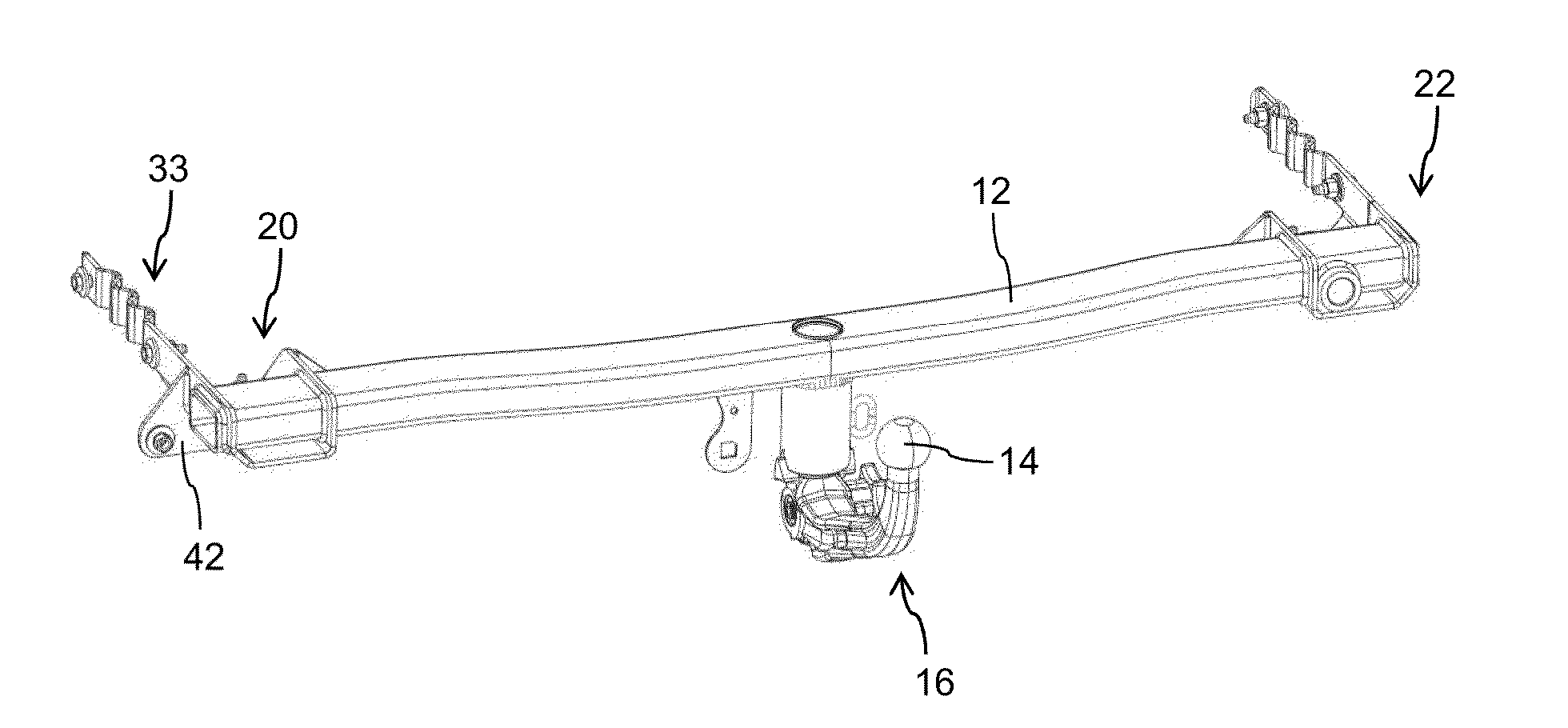
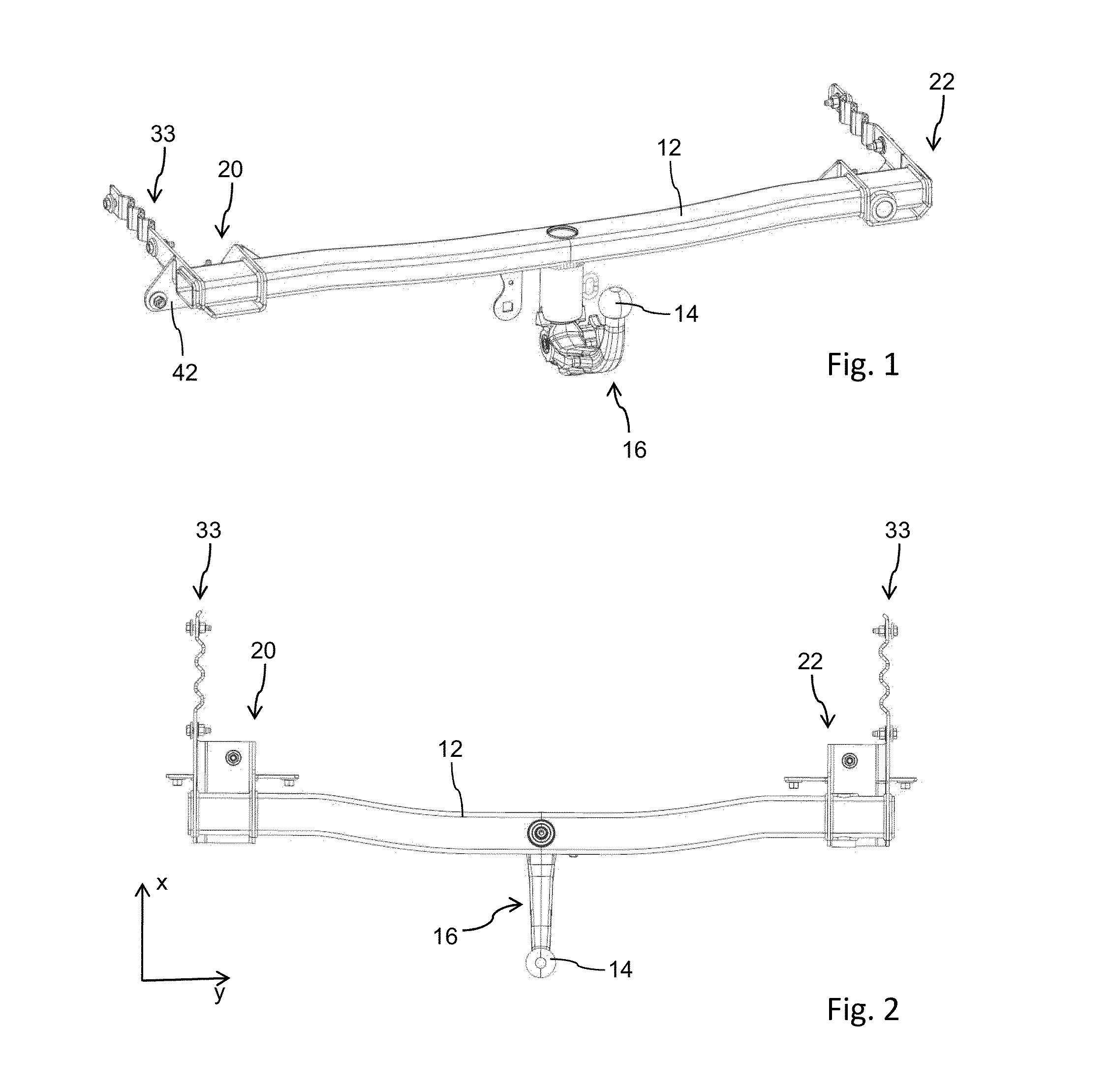
[0035]The rear attachment unit 10 completely shown in the FIG. 1 and FIG. 2 in this case is designed as hitching device. It comprises a support 12 designed as cross beam, which by way of two lateral connecting parts 20, 22 can be connected to a motor vehicle body which in this case is not explicitly shown. The support 12 serves for receiving and arranging a trailer coupling 16, which for example comprises a ball head 14 shown in FIG. 1 and FIG. 2 as coupling member.

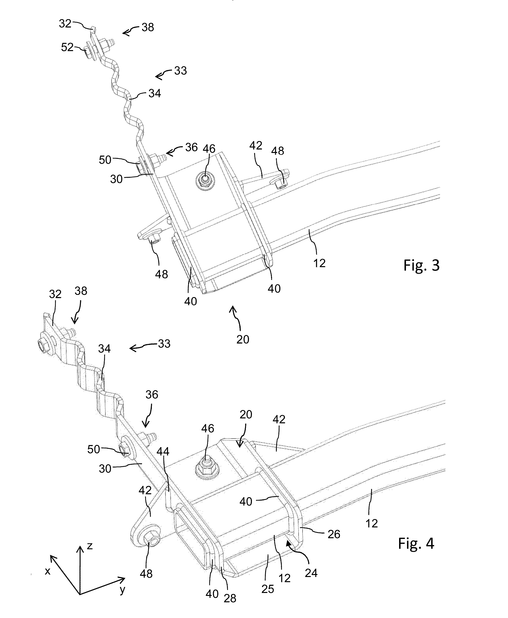
[0036]As is evident by means of the enlarged representation according to the FIGS. 3 and 4, the connecting part 20 has a U-profile like section 24 with two lateral legs 26, 28, which are completely penetrated by the support 12. Here, the support 12 is welde...


PUM


Abstract

A rear attachment unit is provided for a motor vehicle body having a support and at least one connecting part connected thereto for fastening to a rear-end support structure of the body. The connecting part can be connected to the support structure by way of at least one fastening section and includes, but is not limited to a deformation structure with a geometrical shaped design for the absorption of mechanical forces.

Description

CROSS-REFERENCE TO RELATED APPLICATION[0001]This application claims priority to German Patent Application No. 10 2011 112 258.7, filed Sep. 2, 2011, which is incorporated herein by reference in its entirety.TECHNICAL FIELD[0002]The technical field relates to a rear attachment unit of a motor vehicle typically embodied as support device or as hitching device, comprising a cross member embodied for example for the arrangement of a trailer coupling, which by means of two lateral connecting parts can be fastened to the support structure of the vehicle body, in particular to rear-end side members of the body.BACKGROUND[0003]Rear attachment units, such as for example a trailer hitching device or a rear-end extendable support device for bicycles or similar objects for example require an adequately sturdy attachment to the support structure of the motor vehicle, thus to its body. From DE 196 03 873 A1, for example, a hitching device with a trailer coupling and with a hitch block is known. T...

Claims


Application Information

Patent Timeline
Patent Type & Authority Applications(United States)
IPC IPC(8): B60D1/48
CPCB62D21/152B60D1/485B60D1/243
Inventor MATHES, BERNHARDOBERFRANK, MARTIN
Owner GM GLOBAL TECH OPERATIONS LLC
Why Eureka
Try Eureka