Multi-view display device

a display device and multi-view technology, applied in lighting devices, instruments, light sources, etc., can solve the problems of reducing the resolution of the backlight, and having to be at a fixed position

Inactive Publication Date: 2013-03-07
KONINKLIJKE PHILIPS ELECTRONICS NV
View PDF9 Cites 42 Cited by
  • Summary
  • Abstract
  • Description
  • Claims
  • Application Information

AI Technical Summary

Benefits of technology

[0022]A switchable diffuser can be provided for converting the output of the backlight from a directional output to a diffuse output. In this way, the device can be used to provide a single cone output in a desired direction, or else a diffuse output results in a more conventional multiple cone arrangement. This may be more suitable if there are many viewers across the full field of view.
[0023]The backlight can comprise a transparent slab, wherein the slab is shaped with a cross section in the shape of a rectangle with cut-outs, wherein the cut-outs are positioned in areas between the light sources which are beyond the spread of light from the light sources. This design reduces the weight of the backlight by removing material that does not contribute to the optical performance of the backlight.
[0024]If the distance between the pixel plane and the array of lenses, converted into an effec

Problems solved by technology

A drawback of this type of two-view display design is that the viewer has to be at a fixed position, and can only move approximately 3 cm to the left or right.
The parallax barrier arrangement is simple to produce but is not light efficient, especially when the number of views increases.
This sacrifice in resolution increases with the number of views generated.
Thus, a major drawback of using a high number of views i

Method used


Image

  • Multi-view display device
  • Multi-view display device
  • Multi-view display device

Examples


Embodiment Construction

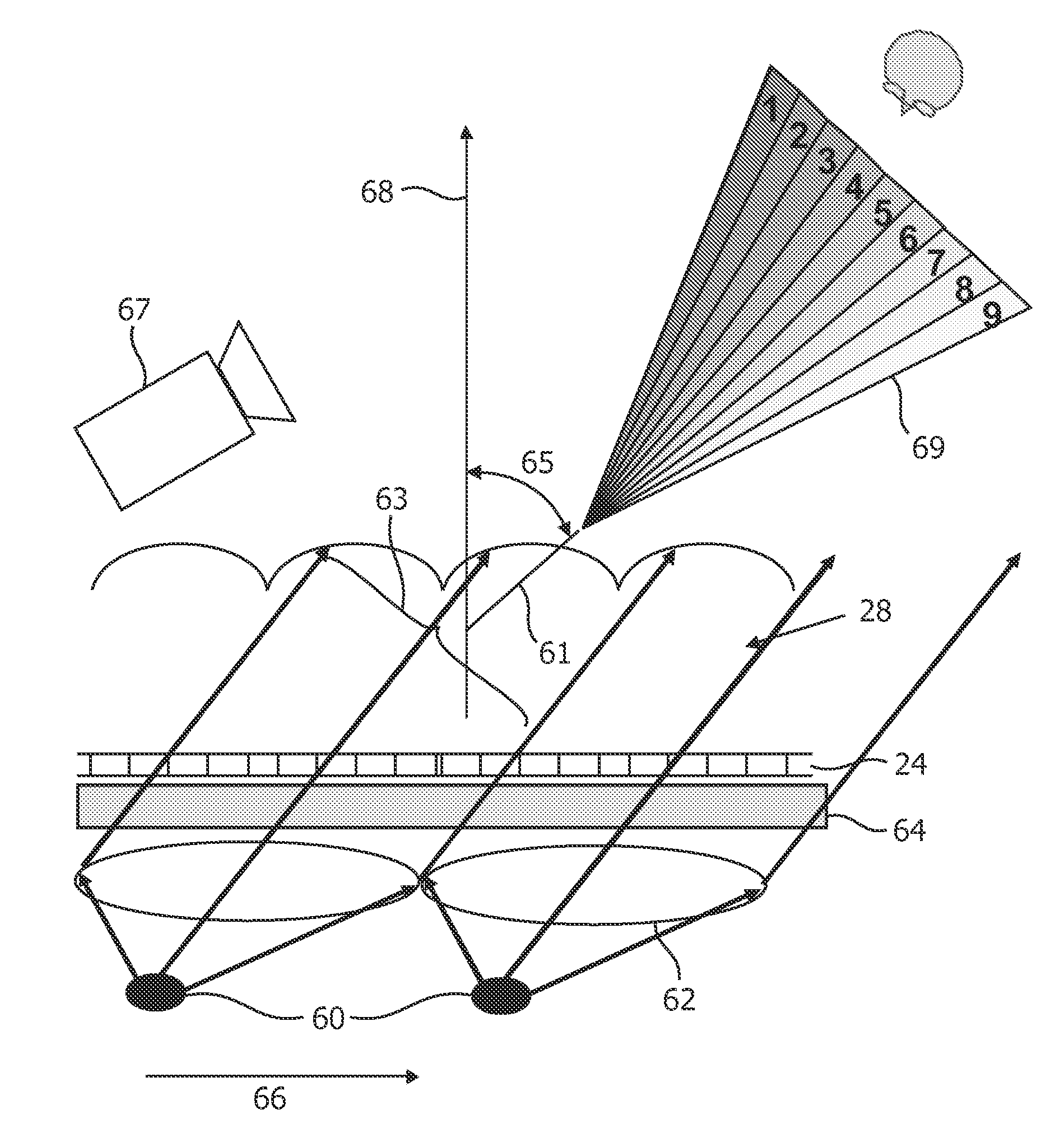
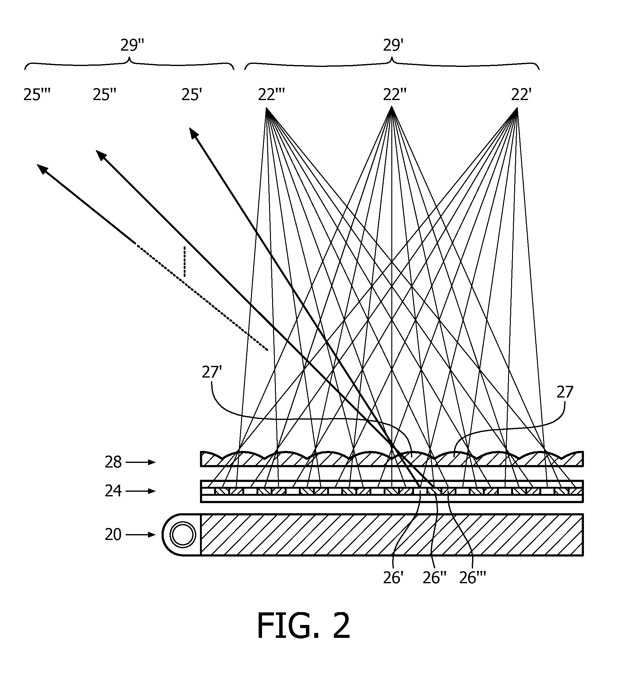
[0050]The invention provides a multi-view display device in which the backlight comprises an arrangement of light sources, wherein each light source, when turned on, directs light to an associated region of the display panel. The light sources are arranged in lines. These lines may be continuous, but they may also be segmented (forming a dotted or dashed line). The lines of light sources can be staggered to match staggered lenses.

[0051]A spread of light from the light source is over a predetermined angle thereby forming an associated output region within the field of view of the display panel from which that region of the display panel illuminated by the light source can be viewed. A display controller adaptively controls the arrangement of light sources such that a partial display output is provided comprising a set of at least three 2D views with no repetition of individual 2D views. A single cone output can be generated by sequentially providing different partial display outputs....


PUM


Abstract

A multi-view display device comprises a pixellated display panel and a backlight comprising an arrangement of light sources (30), wherein each light source, when turned on, illuminates an associated region of pixels of the display panel. A display controller is adapted to control the pixellated display panel and the arrangement of light sources such that a partial display output is provided comprising simultaneously a set of at least three 2D views with no repetition of individual 2D views. This arrangement provides an output with controlled illumination direction of the pixels so that view repetitions are avoided. The output can be a single cone of views, and the location from which the cone of views can be viewed depends on the relationship between the light sources of the backlight which are activated and the display panel.

Description

FIELD OF THE INVENTION[0001]This invention relates to a multi-view display device for providing multiple views within a field of view of the display device of the type that comprises a display panel having pixels for producing a display and an imaging arrangement for directing multiple views to different spatial positions within the field of view of the display device.BACKGROUND OF THE INVENTION[0002]A first example of a multi-view display device includes an imaging arrangement in the form of a parallax barrier that has slits that are sized and positioned in relation to the underlying array of columns and rows of pixels of the display panel. In a two-view design, the viewer is able to perceive a 3D image if his / her head is at a fixed position. The parallax barrier is positioned in front of the display panel and is designed so that light from the odd and even pixel columns is directed towards the left and right eye of the viewer, respectively.[0003]A drawback of this type of two-view...

Claims


Application Information

Patent Timeline
IPC IPC(8): H05B37/02G02B30/27
CPCG02B27/0093G02B27/2214H04N13/047H04N13/045H04N13/0404H04N13/305H04N13/354H04N13/368G02B30/27H04N13/00G02B30/00H05B47/10
Inventor PIJLMAN, FETZEWILLEMSEN, OSCAR HENDRIKUSDESMET, LIEVEN RAF ROGERSLUIJTER, MAARTENDE ZWART, SIEBE TJERKKRIJN, MARCELLINUS PETRUS CAROLUS MICHAEL
Owner KONINKLIJKE PHILIPS ELECTRONICS NV
Why Eureka
Try Eureka