Electromagnetic wave shielding case

a shielding case and electromagnetic technology, applied in the direction of casings/cabinets/drawers, casings/cabinets/drawers details, electrical appliances, etc., can solve the problems of increased cost and weight, reduced weight, and inability to manufacture, so as to reduce cost and weight, reduce costs and weight, and efficiently shield

Inactive Publication Date: 2013-03-07
HYUNDAI MOTOR CO LTD +2
View PDF20 Cites 20 Cited by
  • Summary
  • Abstract
  • Description
  • Claims
  • Application Information

AI Technical Summary

Benefits of technology

[0013]As described above, an electromagnetic wave shielding case according to an exemplary embodiment of the present invention may be only partially formed of metal material to reduce costs and weight. By implementing the above device, partial shielding of electromagnetic waves is possible and thus electromagnetic waves are efficiently shielded between electrical components as well as outside and within the case. Also when the shield is made of metal material is integrally formed with the case made of plastic and manufacturing process may be simplified and enhance shielding efficiency of electromagnetic waves is realized.

Problems solved by technology

However, when metal material is used for manufacturing a whole case, costs and weight are increased and in some case make its manufacture prohibitive.
On the other hand, when special paint is used on the surface of the case, the weight may be reduced, but the shielding efficiency is not sufficient compared to when the metal material is used as the shielding component.

Method used


Image

  • Electromagnetic wave shielding case
  • Electromagnetic wave shielding case
  • Electromagnetic wave shielding case

Examples


Embodiment Construction

[0029]An exemplary embodiment of the present invention will hereinafter be described in detail with reference to the accompanying drawings.

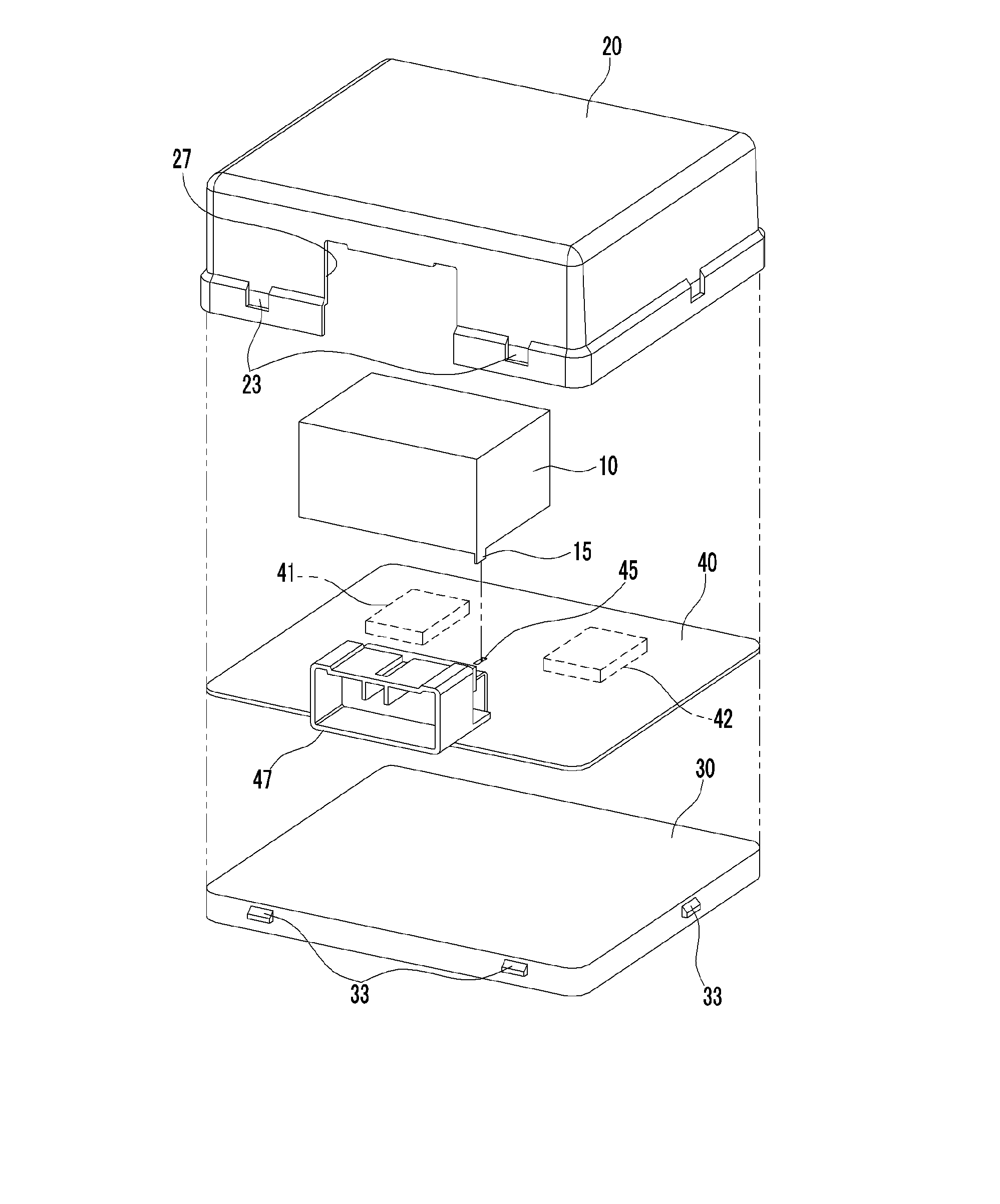
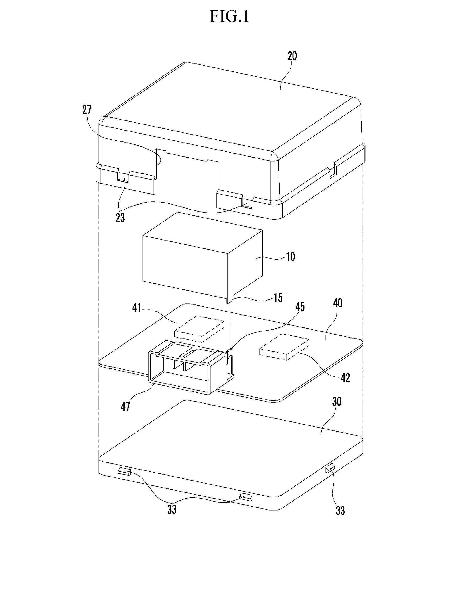
[0030]FIG. 1 and FIG. 2 are an exploded perspective view and perspective view of an electromagnetic wave shielding case according to an exemplary embodiment of the present invention respectively and FIG. 3 is a cross-sectional view along line III-III of FIG. 2.

[0031]Referring to FIGS. 1-3, an electromagnetic wave shielding case according to an exemplary embodiment of the present invention includes a circuit board 40, a shield 10, an upper case 20 and a lower case 30. The circuit board 40 may be, for example, a printed circuit board of which a copper sheet is laminated thereon and electrical components 41 and 42 (e.g., an integrated circuit, a resister, a switch and so on) are disposed thereon. A connector 47 is disposed on and attached to the circuit board 40. The connector 47 may be attached via any means of attaching non-electrical components t...


PUM


Abstract

Disclosed is an electromagnetic wave shielding case. More particularly, an electromagnetic wave shielding case for a circuit board provided with a connector includes an upper case configured to cover an upper portion of the circuit board, and a lower case configured to form an internal space when the upper case is connected therewith, wherein the circuit board is attached to an upper surface of the lower case. A shield configured to shield electromagnetic waves, is attached to the circuit board within the internal space formed by the upper case and the lower case to shield components (both inside the case and out) from electromagnetic waves.

Description

CROSS-REFERENCE TO RELATED APPLICATION[0001]This application claims priority to and the benefit of Korean Patent Application No. 10-2011-0088466 filed in the Korean Intellectual Property Office on Sep. 1, 2011, the entire contents of which are incorporated herein by reference.BACKGROUND OF THE INVENTION[0002](a) Field of the Invention[0003]The present invention relates to an electromagnetic wave shielding case. More particularly, the present invention relates to an electromagnetic wave shielding case for shielding electromagnetic waves efficiently from a circuit board.[0004](b) Description of the Related Art[0005]Conventionally, metal material or special paint has been used for manufacturing cases that shields electromagnetic waves from coming in contact with various components. However, when metal material is used for manufacturing a whole case, costs and weight are increased and in some case make its manufacture prohibitive. On the other hand, when special paint is used on the sur...

Claims


Application Information

Patent Timeline
Patent Type & Authority Applications(United States)
IPC IPC(8): H05K5/02
CPCH05K9/0026
Inventor MIN, MYOUNG KIJUNG, CHANG-SEAK
Owner HYUNDAI MOTOR CO LTD
Why Eureka
Try Eureka