Autonomous surface treating appliance

a technology for treating appliances and surfaces, applied in steering controls, non-vehicle mounted steering controls, braking systems, etc., can solve problems such as difficulty in turning a robot on the spot, and achieve the effects of improving traction, maintaining strong traction, and enhancing the drive arrangemen

Inactive Publication Date: 2013-03-14
DYSON TECH LTD
View PDF44 Cites 17 Cited by
  • Summary
  • Abstract
  • Description
  • Claims
  • Application Information

AI Technical Summary

Benefits of technology

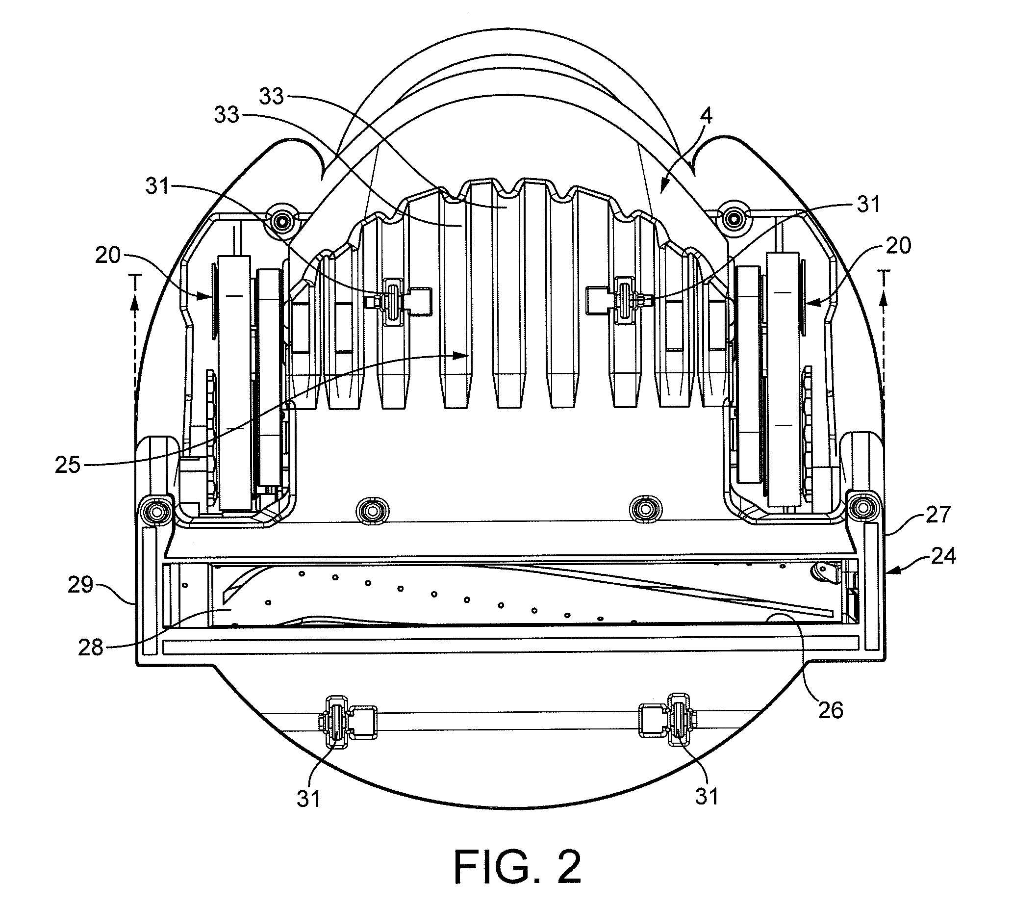
[0009]This ramped climbing surface relative to the adjacent surface to be treated improves the ability of the robot to climb over imperfections in the surface to be treated, as well as over raised obstacles such as electrical cables / flexes or edges of rugs for example. Moreover, due to the portion of the track forward of the trailing wheel, which is inclined relative to the horizontal, a small contact patch is maintained which provides a maneuvering benefit since it does not suffer the extent of slippage that would be experienced if a significant portion of the track was in contact with the floor surface. This is particularly true on carpeted surfaces where an elongate contact patch as exemplified by known tank-track configurations makes it difficult for a robot to turn on the spot. In contrast to this, the mobile robot of the invention is provided with the climbing advantages of a tracked climbing surface and the maneuvering advantages of a small contact patch in the same way as a plain wheel.
[0011]For simplicity and cost, the motor is an electric motor and, more specifically, a brushless DC motor. Other motor drives are possible such as a hydraulic motor drive, albeit at increased cost and weight.
[0012]Although the leading wheel may be driven directly by the motor, in the exemplary embodiment a transmission unit is provided to transmit drive from the motor to the leading wheel. The enables the speed of the motor to be down-geared whilst increasing torque and ensuring control accuracy.
[0014]When travelling over rough surfaces, for example thick pile carpet, improved traction is required. Thus, in an enhancement of the drive arrangement, biasing means is provided intermediate the transmission case and the linkage member which urges the trailing wheel towards the surface to be treated. Thus, if the chassis is cause to raise due to contact with an obstacle or surface feature, the trailing wheel will be urged into contact with the surface therefore maintaining strong traction.
[0015]In order to prevent objects from fouling the tracks the linkage member may include a guard member that at least partially fills a volume bounded by the leading wheel, the trailing wheel and the inner surfaces of the track. This reduces the likelihood that objects such as grit or stones will enter the nip between the track and the wheels, therefore improving the reliability of the traction units.
[0016]A further traction enhancement is provided by the configuration of the trailing wheel. The trailing wheel may rim portion adjacent to and having a larger diameter than a track engaging surface of the trailing wheel. Optionally, the rim portion may extend to the same radial position as the outer surface of the track and may be provided with a smooth or serrated profile. In this embodiment, since the rim portion extends to a radium comparable with the track radius, in circumstances in which robot is travelling over a soft surface such as a rug or carpet, the track will tend to sink into the pile of the carpet whereby the serrated edge of the rim portion will tend to engage the carpet and provide the robot with increased traction. However, on hard surfaces, only the track will contact the floor surface which will benefit the maneuvering ability of the robot.

Problems solved by technology

This is particularly true on carpeted surfaces where an elongate contact patch as exemplified by known tank-track configurations makes it difficult for a robot to turn on the spot.

Method used


Image

  • Autonomous surface treating appliance
  • Autonomous surface treating appliance
  • Autonomous surface treating appliance

Examples


Embodiment Construction

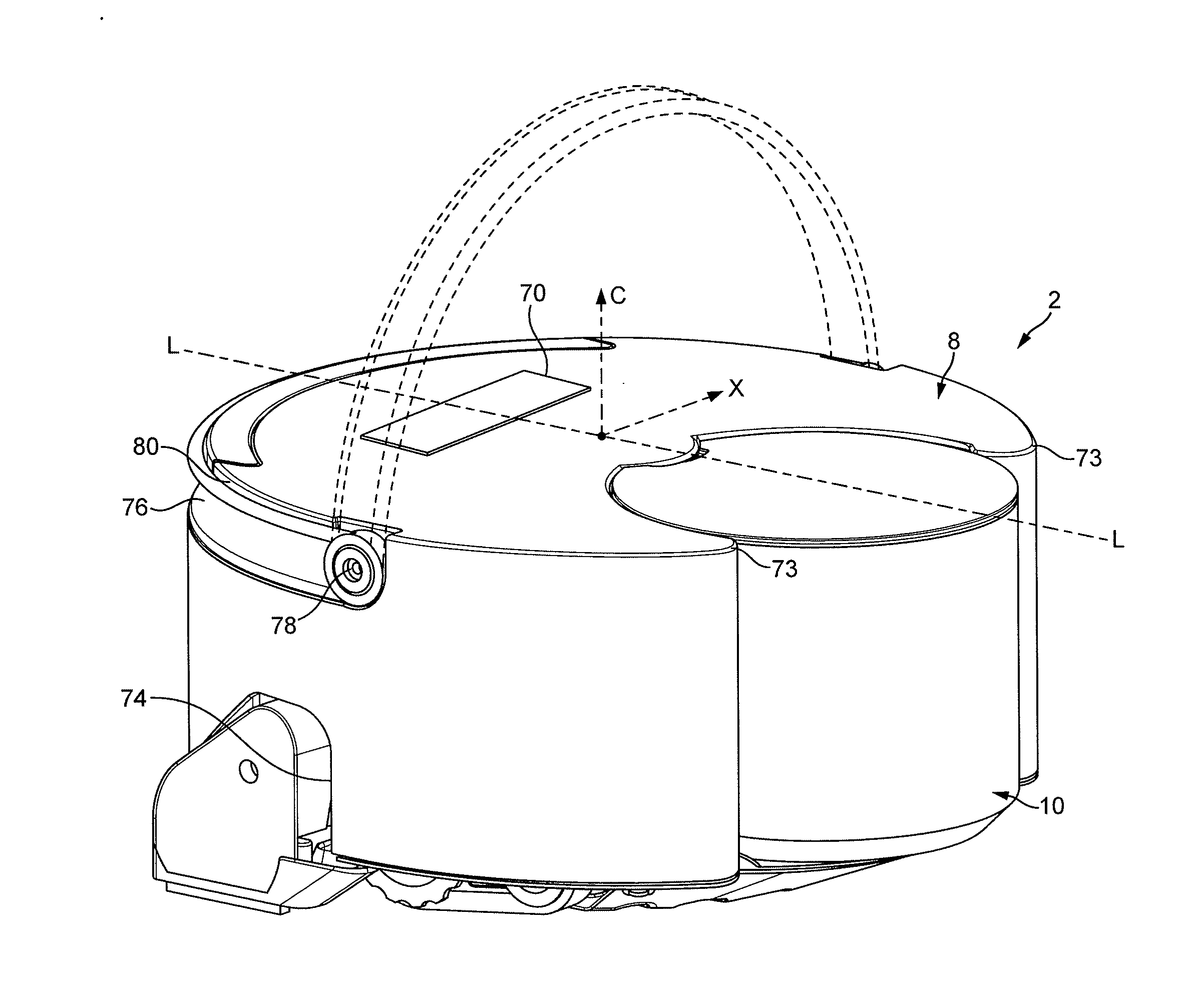
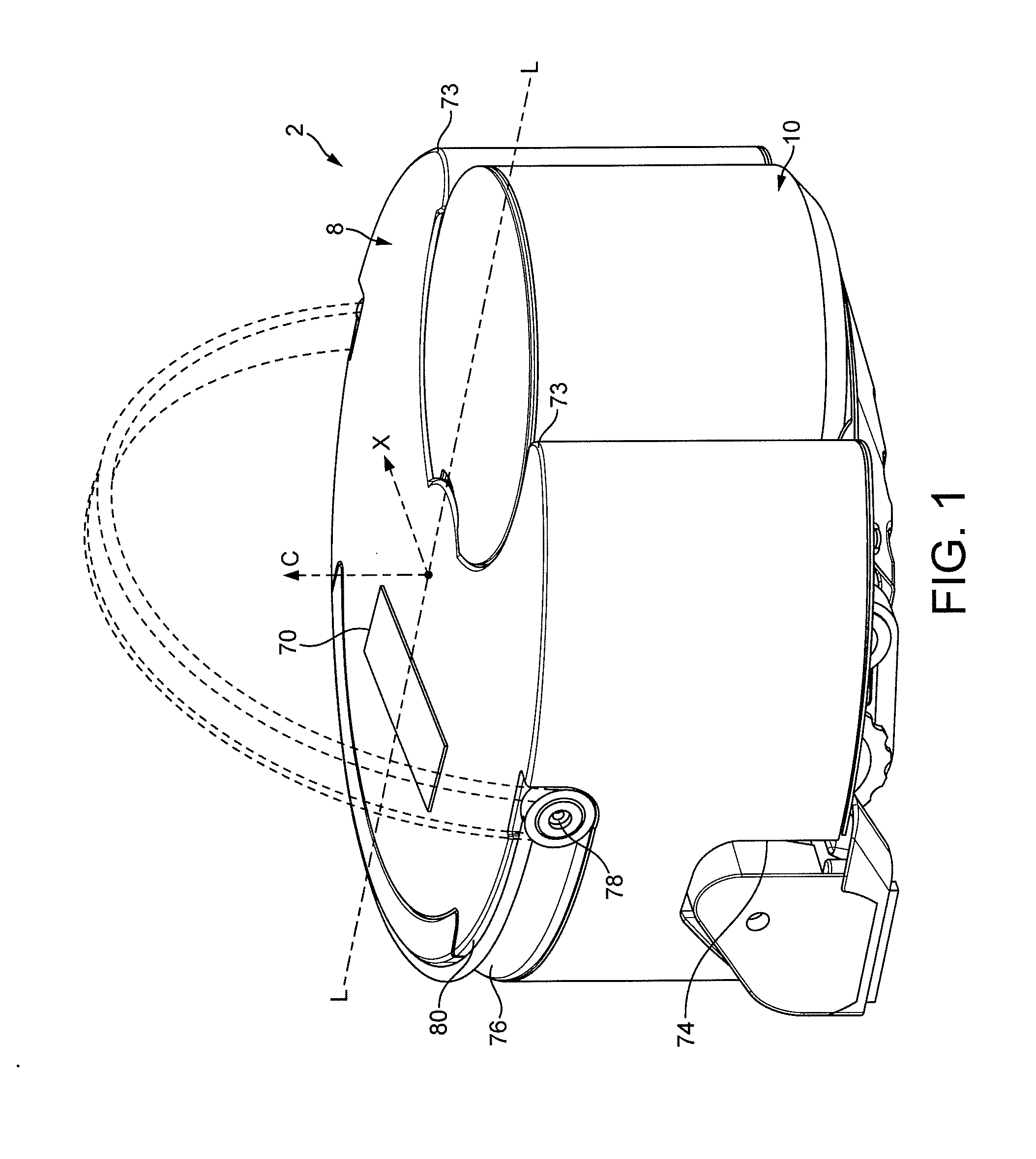
[0032]With reference to FIGS. 1, 2, 3, 4 and 5 of the drawings, an autonomous surface treating appliance in the form of a robotic vacuum cleaner 2 (hereinafter ‘robot’) comprises has a main body having four principal assemblies: a chassis (or sole plate) 4, a body 6 which is carried on the chassis 4, a generally circular outer cover 8 which is mountable on the chassis 4 and provides the robot 2 with a generally circular profile, and a separating apparatus 10 that is carried on a forward part of the body 6 and which protrudes through a complementary shaped cut-out 12 of the outer cover 8.

[0033]For the purposes of this specification, the terms ‘front’ and ‘rear’ in the context of the robot will be used in the sense of its forward and reverse directions during operation, with the separating apparatus 10 being positioned at the front of the robot. Similarly, the terms ‘left’ and ‘right’ will be used with reference to the direction of forward movement of the robot. As will be appreciated...


PUM


Abstract

An autonomous surface treating appliance comprising a chassis having a drive arrangement and a control system interfaced to the drive arrangement so as enable control of the appliance across a surface to be treated, wherein the drive arrangement comprises at least one traction unit, each traction unit comprising a surface-engaging track constrained around a leading wheel and a trailing wheel, the leading wheel and the trailing wheel being arranged so that a track portion opposing the floor surface and extending between the leading and trailing wheels defines a ramped climbing surface.

Description

REFERENCE TO RELATED APPLICATIONS[0001]This application claims the priority of United Kingdom Application No. 1115603.1, filed Sep. 9, 2011, the entire contents of which are incorporated herein by reference.FIELD OF THE INVENTION[0002]This invention relates to an autonomous surface treating appliance, such as a mobile robotic vacuum cleaner, and also to a drive arrangement for such a machine.BACKGROUND OF THE INVENTION[0003]Mobile robots are increasingly commonplace and are used in such diverse fields as space exploration, lawn mowing and floor cleaning. The last decade has seen particularly rapid advancement in the field of robotic floor cleaning devices, especially vacuum cleaners, the primary objective of which is to navigate a user's home autonomously and unobtrusively whilst cleaning the floor. The invention will be described in the context of a robotic vacuum cleaner but it is also applicable in general to any type of mobile robot platform, such as robotic lawn mowers.[0004]Co...

Claims


Application Information

Patent Timeline
Patent Type & Authority Applications(United States)
IPC IPC(8): B62D55/06A47L5/00G05D1/02
CPCA47L9/009B62D55/075A47L2201/04B60L1/003B60L15/2036B60L2200/40B60L2220/44B60L2240/421B60L2240/423B60L2260/32B60L50/52B60L58/12Y02T10/64Y02T10/70Y02T10/7072Y02T10/72Y02T90/14A01D34/00A01D69/00A47L9/00A47L9/28
Inventor DYSON, JAMESGAMMACK, PETER DAVIDVANDERSTEGEN-DRAKE, MARK STAMFORDBOTT, PAUL JOSHUA
Owner DYSON TECH LTD
Why Eureka
Try Eureka