Turning guide for combustion fuel nozzle in gas turbine and method to turn fuel flow entering combustion chamber

a technology of combustion fuel nozzle and turning guide, which is applied in the direction of machines/engines, mechanical equipment, lighting and heating apparatus, etc., can solve the problems of fuel nozzles posing flame holding risks, fuel nozzle hardware being destroyed, and localized variations in air and fuel mixtur

Active Publication Date: 2013-03-14
GENERAL ELECTRIC CO
View PDF4 Cites 29 Cited by
  • Summary
  • Abstract
  • Description
  • Claims
  • Application Information

AI Technical Summary

Problems solved by technology

Zones of low velocity airflow in the fuel nozzle also pose a flame holding risk inside the nozzle as low velocity zones provide an area for a flame to anchor inside the fuel nozzle.
A flame in the fuel nozzle can destroy the hardware of the nozzle.
In addit...

Method used


Image

  • Turning guide for combustion fuel nozzle in gas turbine and method to turn fuel flow entering combustion chamber
  • Turning guide for combustion fuel nozzle in gas turbine and method to turn fuel flow entering combustion chamber
  • Turning guide for combustion fuel nozzle in gas turbine and method to turn fuel flow entering combustion chamber

Examples


Embodiment Construction

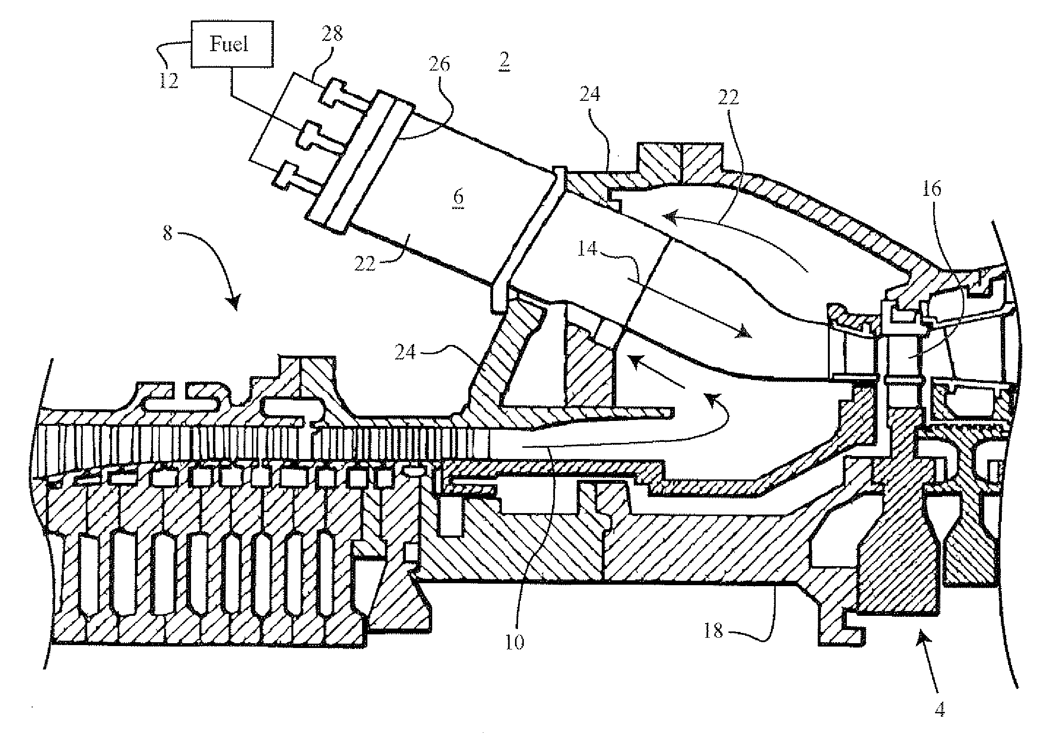
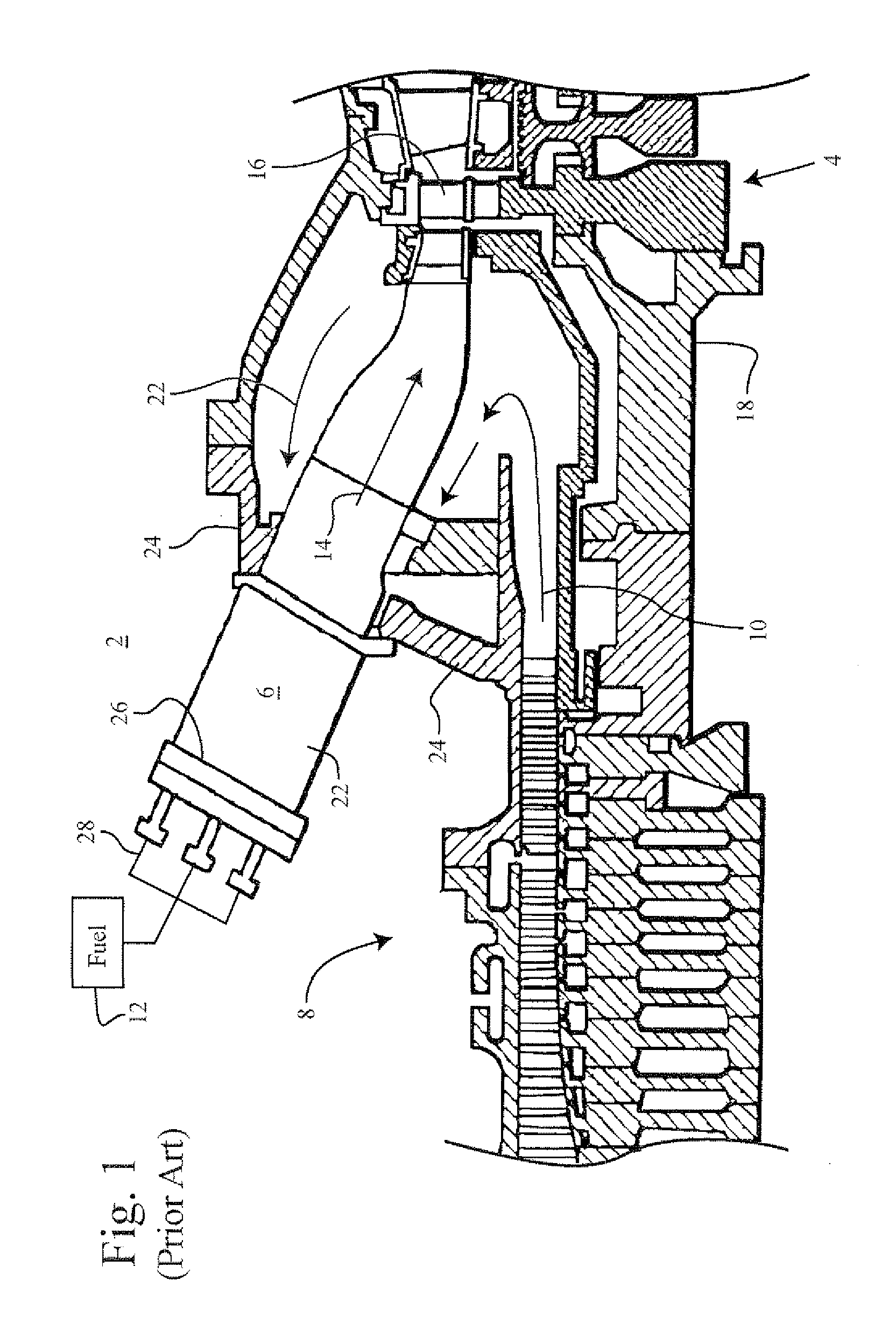
[0021]FIG. 1 is side view, showing in partial cross section, a conventional gas turbine engine 2 including an axial turbine 4, an annular array of combustion chambers 6, and an axial compressor 8 which generates compressed air 10 ducted to the combustion chambers. Fuel 12 is injected into the combustion chambers and mixes with the compressed air. The air fuel mixture combusts in the combustion chambers and hot combustion gases 14 flow from the chambers to the turbine to drive the turbine buckets 16 to rotate the turbine 4. The rotation of the turbine turns the compressor via the shaft 18 connecting the turbine and compressor. The rotation of the compressor generates the compressed air for the combustion chambers.

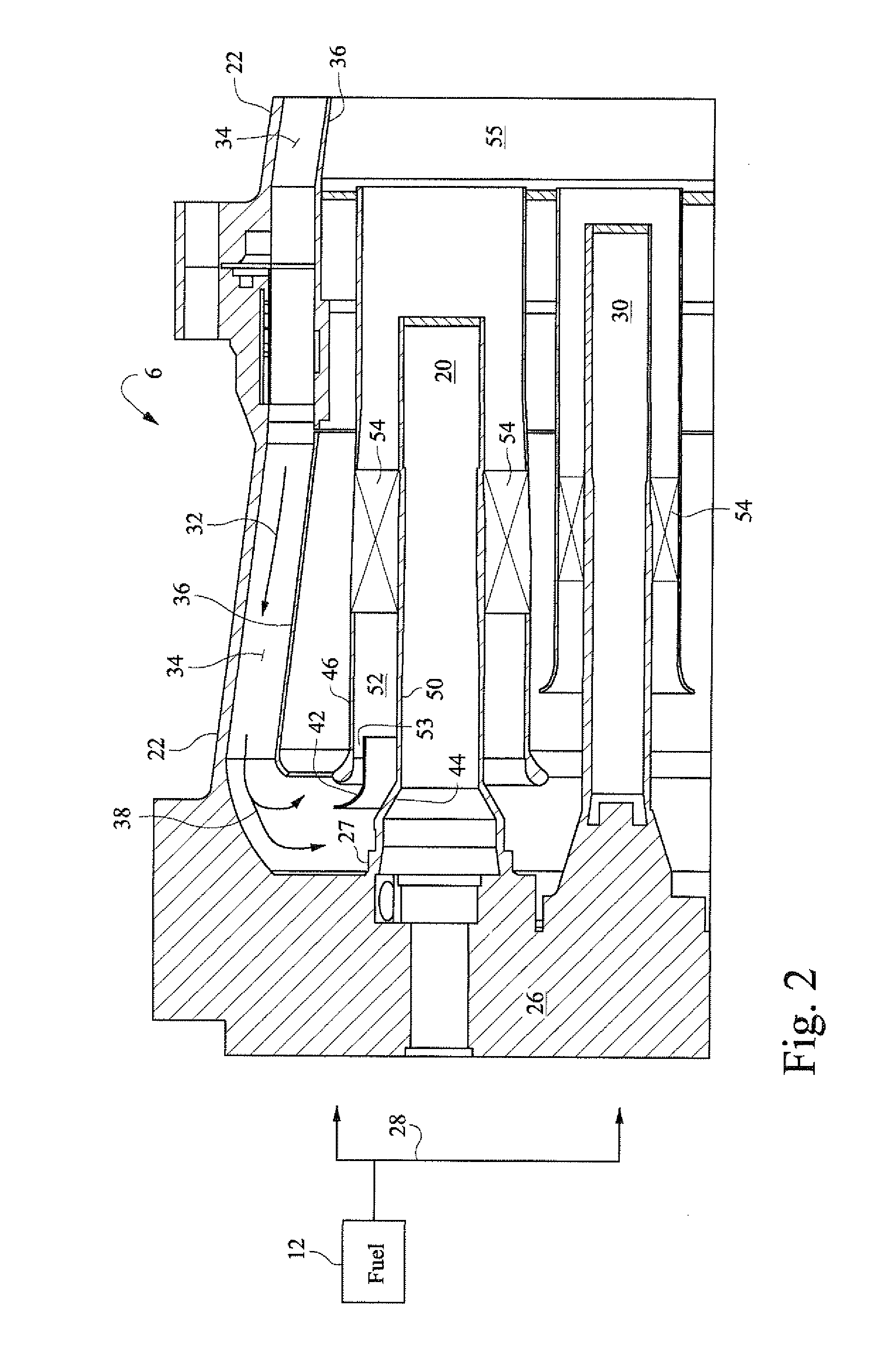
[0022]FIG. 2 is a cross sectional drawing of a portion of a combustion chamber 6 to show a fuel nozzle assemblies 20. Each combustion chamber 6, also referred to as a “can”, includes a substantially cylindrical sleeve 22 secured to the casing 24 of the gas turbine near the d...


PUM


Abstract

A fuel nozzle assembly for a gas turbine, the assembly including: a cylindrical center body; a cylindrical shroud coaxial with and extending around the center body, and a turning guide having an downstream edge extending in a passage between the center body and an inlet to the shroud, wherein the turning guide extends only partially around the center body.

Description

[0001]The invention relates to fuel combustion in a gas turbine, and particularly relates to guiding compressed air to a combustion zone in a combustor.BACKGROUND OF THE INVENTION[0002]A gas turbine combustor mixes large quantities of fuel and compressed air, and burns the resulting air and fuel mixture. Conventional combustors for industrial gas turbines typically include an annular array of cylindrical combustion “cans” in which air and fuel are mixed and combustion occurs. Compressed air from an axial compressor flows into the combustor. Fuel is injected through fuel nozzle assemblies that extend into each can. The mixture of fuel and air burns in a combustion chamber of each can. The combustion gases discharge from each can into a duct that leads to the turbine.[0003]Pressurized air from the compressor enters a combustion can at the back end of the can, which is the same end from which hot combustion gases flow from the can to the turbine. The compressed air flows through an ann...

Claims


Application Information

Patent Timeline
IPC IPC(8): F02C7/22
CPCF23R3/26F23R3/10
Inventor STEWART, JASON THURMAN
Owner GENERAL ELECTRIC CO
Why Eureka
Try Eureka