Micro Electrical Mechanical System with Bending Deflection of Backplate Structure

a micro-electrical mechanical and backplate technology, applied in the direction of semiconductor electrostatic transducers, diaphragms of transducers, instruments, etc., can solve the problems of large volume manufacture, amplitude of membrane movement typically limited by the thickness of the sacrificial layer

Active Publication Date: 2013-03-14
INFINEON TECH AG
View PDF8 Cites 33 Cited by
  • Summary
  • Abstract
  • Description
  • Claims
  • Application Information

AI Technical Summary

Problems solved by technology

This leads to potentially large volume manufacture.
In use, the amplitude of the membrane movement is typically limited by approximately the thickness of the sacrificial layer because of structures formed on the sacrificial layers during the manufacturing process prior to (partly) removing the sacrificial layer, thus leaving the formed structures.

Method used


Image

  • Micro Electrical Mechanical System with Bending Deflection of Backplate Structure
  • Micro Electrical Mechanical System with Bending Deflection of Backplate Structure
  • Micro Electrical Mechanical System with Bending Deflection of Backplate Structure

Examples


Embodiment Construction

[0032]In the following description, a plurality of details are set forth to provide a more thorough explanation of embodiments of the present invention. However, it will be apparent to one skilled in the art, that embodiments of the present invention may be practiced without these specific details. In other instances, well-known structures and devices are shown in schematic cross-sectional views or top-views rather than in detail in order to avoid obscuring embodiments of the present invention. In addition, features of the different embodiments described hereinafter, may be combined with other features and with other embodiments, unless specifically noted otherwise.

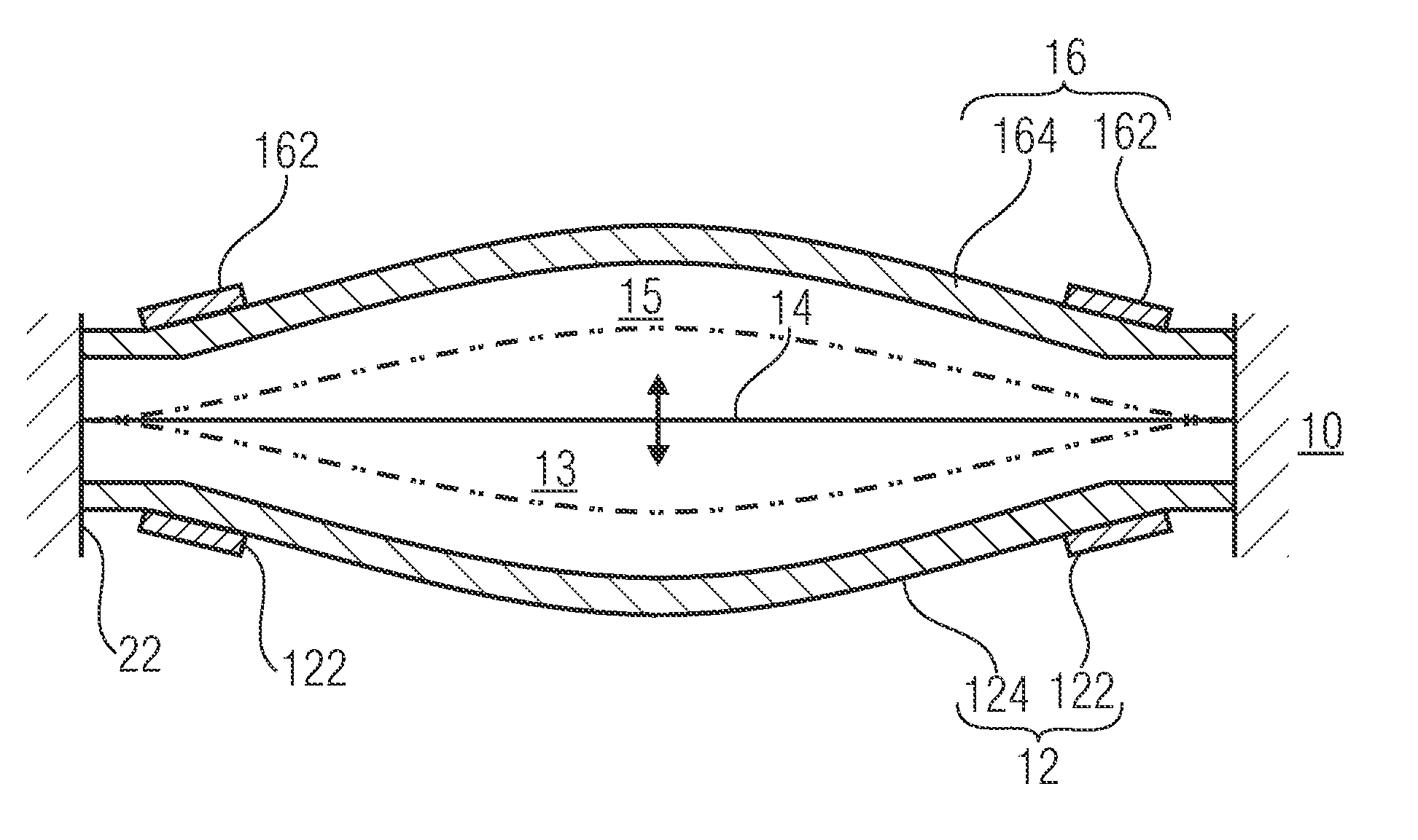
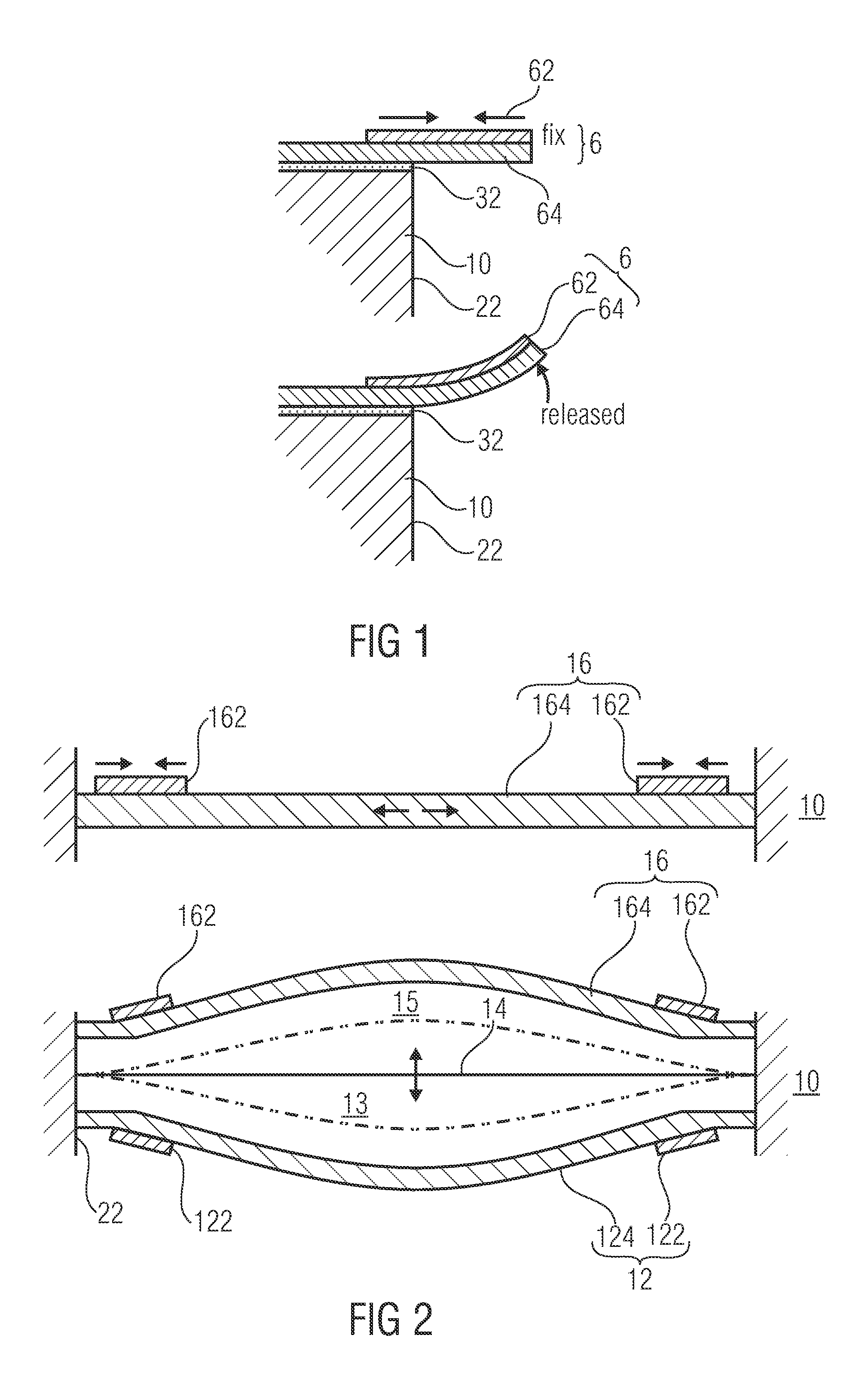
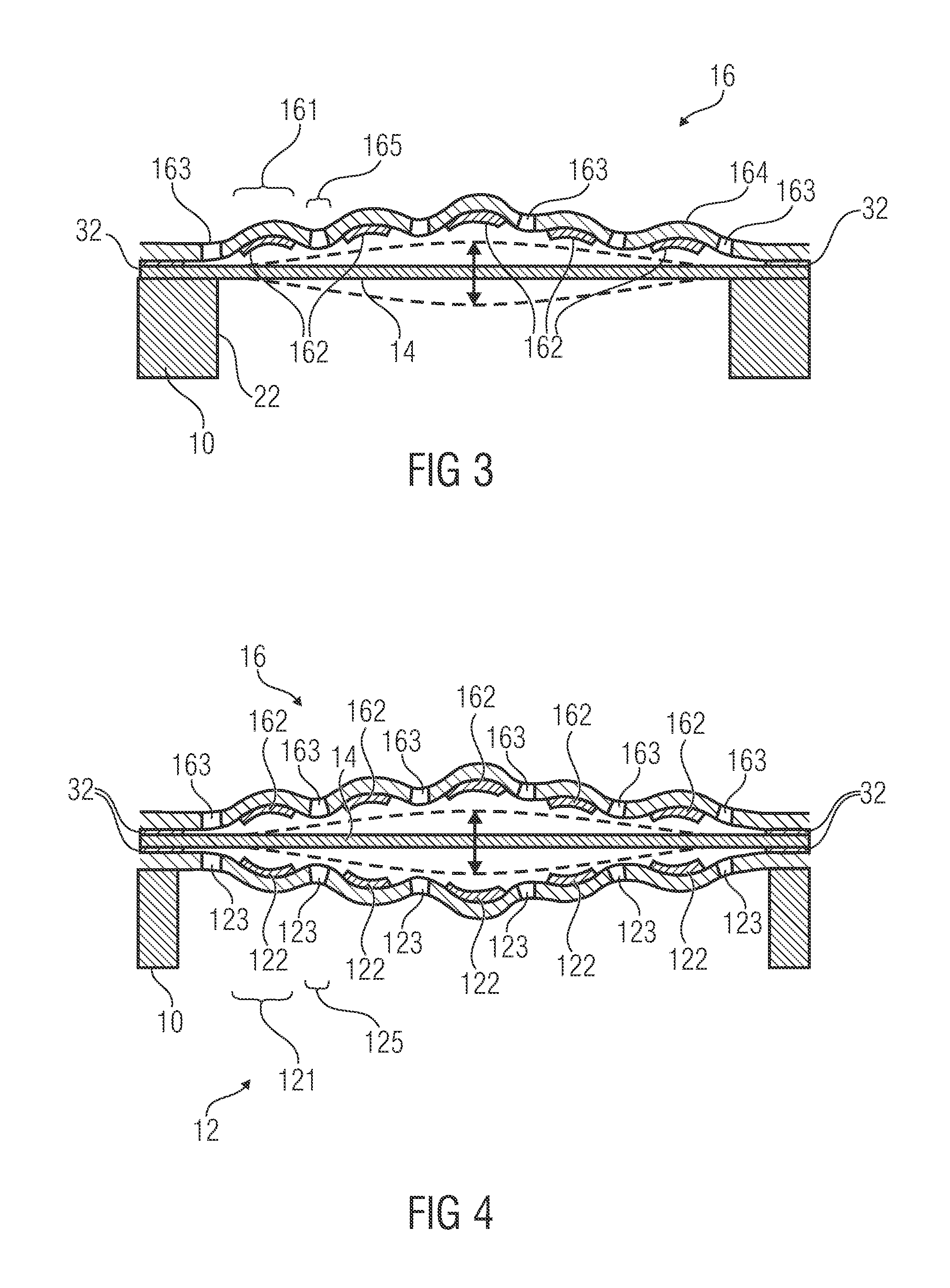
[0033]The possible applications of the teachings disclosed herein are for sensors (e.g., microphones) and for actuators (e.g., micro speakers). In particular, the teachings disclosed herein may be applied in connection with a digital speaker operating in contact mode (the membrane mechanically contacting the backplate(s) ...


PUM


Abstract

A micro electrical mechanical system includes a membrane structure and a backplate structure. The backplate structure includes a backplate material and at least one pre-tensioning element mechanically connected to the backplate material. The at least one pre-tensioning element causes a mechanical tension on the backplate material for a bending deflection of the backplate structure in a direction away from the membrane structure.

Description

TECHNICAL FIELD[0001]Embodiments of the present invention relate to micro electrical mechanical systems (MEMS) comprising a membrane structure and a backplate structure. Some embodiments of the present invention relate to a method for manufacturing a micro electrical mechanical system.BACKGROUND[0002]In the technical field of transducers miniaturization is one of the major research interests. At the same time, typical performance figures of the transducers, such as signal-to-noise ratio or dynamic range should be maintained at a reasonable level. Micro electrical mechanical systems (MEMS) have been targeted for these applications as they are potentially small scaled, on the order of tens of micrometers, and for their compatibility with semiconductor-like processes. This leads to potentially large volume manufacture. Devices that can be achieved using MEMS fabrication processes are, for example, pressure sensors, ultrasonic transducers, loudspeakers, and microphones. Typically these ...

Claims


Application Information

Patent Timeline
Patent Type & Authority Applications(United States)
IPC IPC(8): H01L29/84H01L21/00
CPCG01L9/0016B81C1/00158B81B2201/0257B81B2203/0127B81C2201/0167H04R1/005H04R2440/05H04R7/14H04R7/24H04R19/005H04R31/003H04R2201/003H04R7/125B81B3/00B81C1/00B81C1/00476
Inventor DEHE, ALFONS
Owner INFINEON TECH AG
Why Eureka
Try Eureka