Mechanism for signaling buffer status information

a technology of status information and signaling buffer, which is applied in the field of signaling buffer status information, can solve the problems of device battery life, fundamental technology limitations, and still present limitations, and achieve the effect of reducing the amount of transmission resources and being easy to implemen

Active Publication Date: 2013-03-14
AVAGO TECH INT SALES PTE LTD
View PDF8 Cites 69 Cited by
  • Summary
  • Abstract
  • Description
  • Claims
  • Application Information

AI Technical Summary

Benefits of technology

[0043]By virtue of the proposed solutions, it is possible to signal buffer status information for communication over licensed and unlicensed spectrum in such a manner that the network, i.e. a corresponding communication network control element, obtains information about how many resources the device needs. That is, it is possible that the device, e.g. a UE, can indicate to the network that it needs actually a reduced amount of resources for transmission on one spectrum, e.g. a licensed, due to offloading traffic from this spectrum. Furthermore, according to examples of embodiments of the invention, the proposed mechanism is easy to be implemented as existing signaling procedures can be used. Furthermore, it is possible to utilize a reinterpretation of current specified messages but the scheme works also without reinterpretation

Problems solved by technology

However, such an approach presents fundamental technology limitations from the point of view of e.g. device battery life (due to the extensive GPS usage), signaling load to the network (due to the required uplink bursty traffic) and simplicity (due to the “proactive” behavior required of the user, e.g. the “check in”).
While the use of an unlicensed-spectrum communication can address some of the aspects mentioned earlier, it still presents some limitations.
For example, discovery processes are being defined based on direct message exchanges and thus not optimal for operation over longer ranges (hundreds of meters or more), or preserve a reasonable battery life.
For the same reason, an unlicensed option cannot be expected to scale among a large number of devices.

Method used


Image

  • Mechanism for signaling buffer status information
  • Mechanism for signaling buffer status information
  • Mechanism for signaling buffer status information

Examples


Embodiment Construction

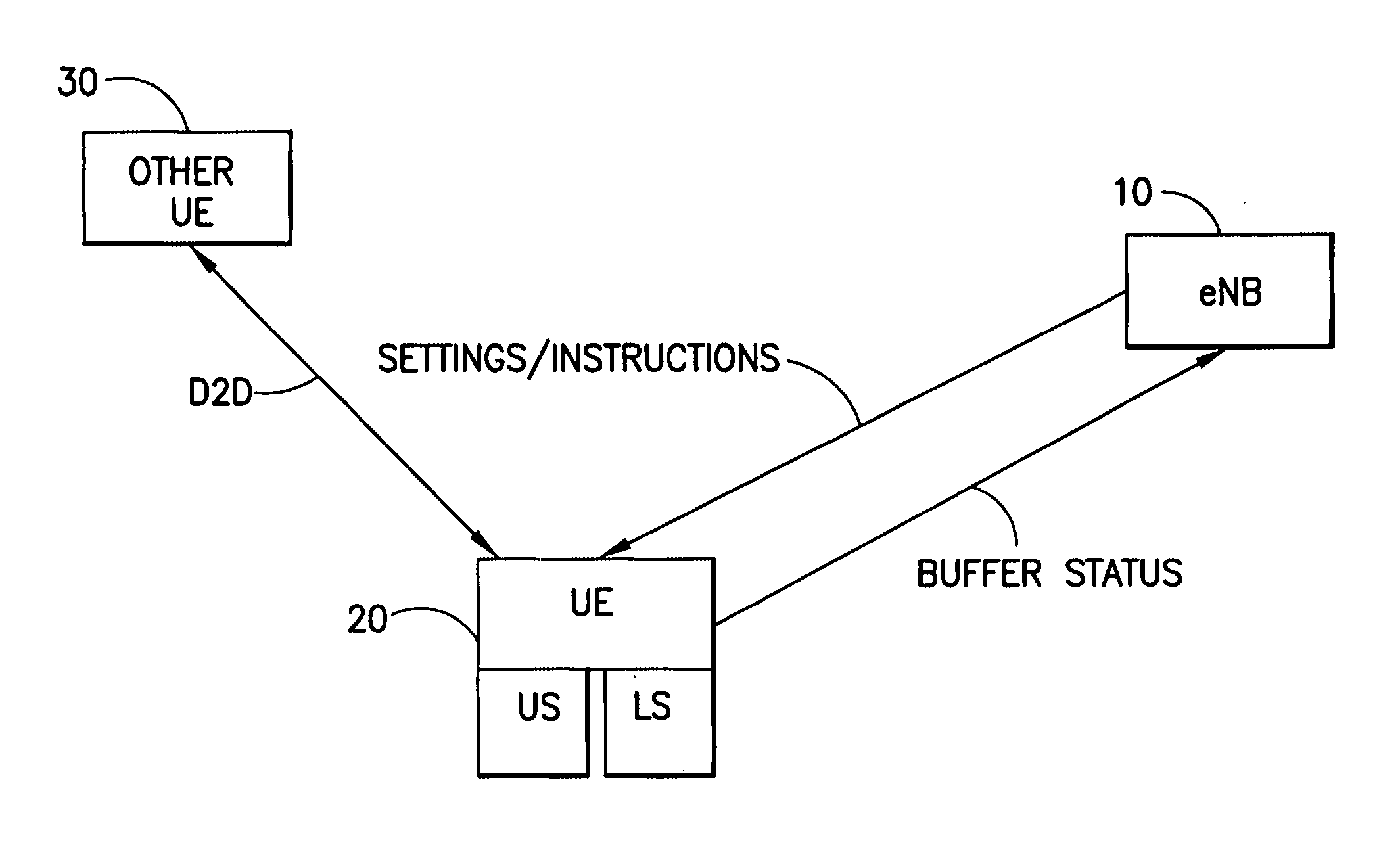
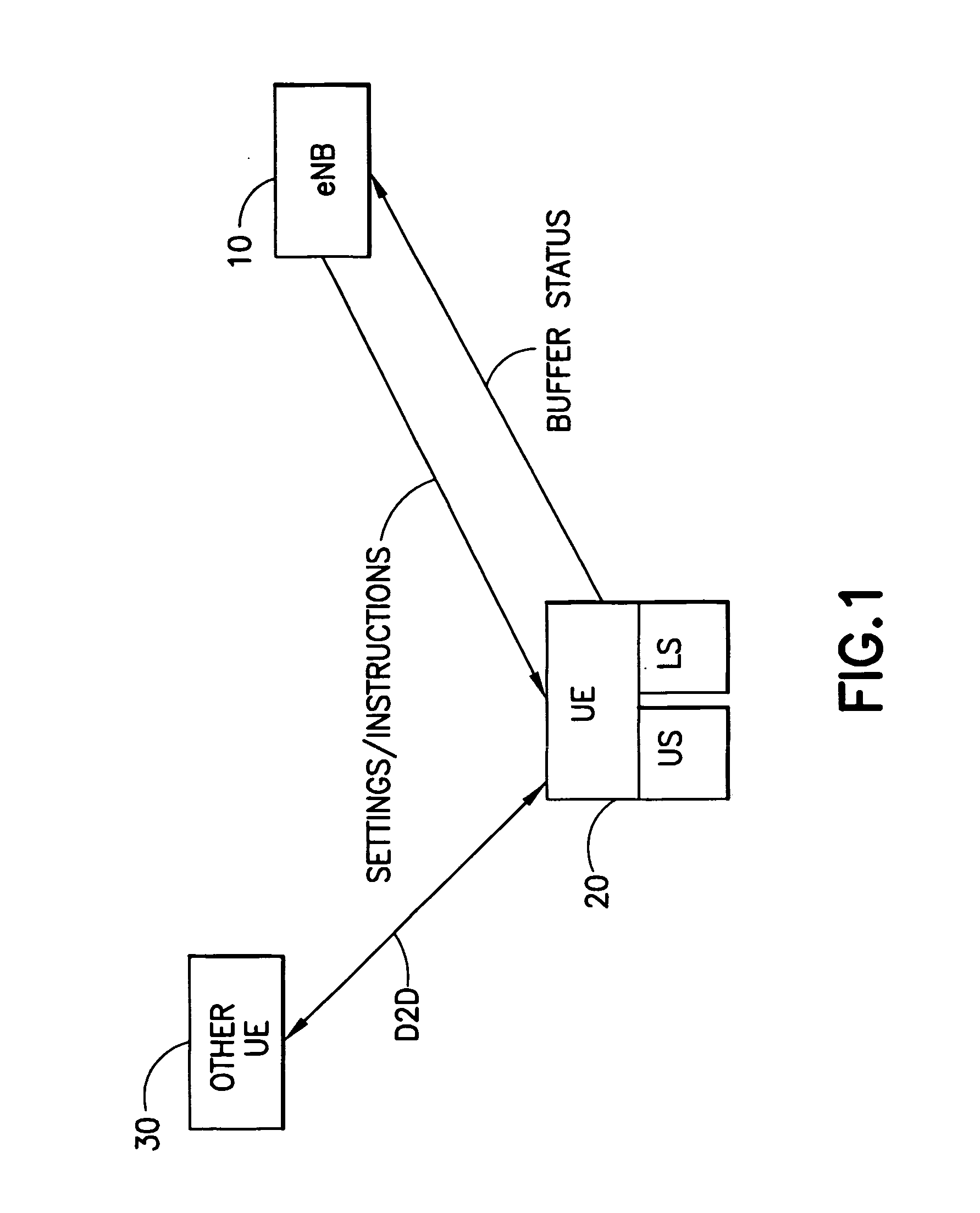
[0052]In the following, examples and embodiments of the present invention are described with reference to the drawings. For illustrating the present invention, the examples and embodiments will be described in connection with a cellular communication network based on a 3GPP LTE system. However, it is to be noted that the present invention is not limited to an application using such types of communication system, but is also applicable in other types of communication systems and the like.

[0053]A basic system architecture of a communication system where examples of embodiments of the invention are applicable may comprise a commonly known architecture of one or more communication networks comprising a wired or wireless access network subsystem and a core network. Such an architecture may comprise one or more access network control elements, radio access network elements, access service network gateways or base transceiver stations, such as a base station (BS) or eNB, with which a commu...


PUM


Abstract

There is provided a mechanism for reporting buffer status information to a communication network control element when transmission via both a licensed and an unlicensed spectrum is conducted and offloading of traffic is executed. After an offloading value indicating the amount of traffic which can be offloaded from a transmission over a licensed spectrum to a transmission over an unlicensed spectrum is estimated, the UE determines a buffer size of at least one transmission buffer used in a transmission over the licensed spectrum and the unlicensed spectrum. Then, buffer status information is sent to the eNB wherein the estimated offloading value is considered. The eNB can then allocate resources for the transmission over the licensed band while benefits by the offloading to the unlicensed band are considered in the resource allocation.

Description

BACKGROUND OF THE INVENTION[0001]1. Field of the Invention[0002]The present invention relates to a mechanism usable for signaling buffer status information for communication over licensed and unlicensed spectrum. In particular, the present invention is related to apparatuses, methods and computer program products providing a mechanism by means of which buffer status information can be signaled to the network wherein communication resources in licensed and unlicensed spectrums are considered, in particular in an offloading case where traffic is offloaded from a transmission via one spectrum to a transmission via another spectrum.[0003]2. Related Background Art[0004]Prior art which is related to this technical field can e.g. be found by the technical specification 3GPP TS 36.321, for example according to version 10.2.0.[0005]The following meanings for the abbreviations used in this specification apply:[0006]ABS: actual buffer size[0007]BS: base station[0008]BSR: buffer status report[0...

Claims


Application Information

Patent Timeline
Patent Type & Authority Applications(United States)
IPC IPC(8): H04W24/00H04L12/26
CPCH04W72/1284H04L43/08H04W28/08H04W28/0278H04W16/14H04W72/21
Inventor KOSKELA, TIMOHAKOLA, SAMI-JUKKATURTINEN, SAMULI
Owner AVAGO TECH INT SALES PTE LTD
Why Eureka
Try Eureka