
Mobile communication method and mobile station

a mobile station and communication method technology, applied in the direction of signal allocation, transmission path sub-channel allocation, connection management, etc., can solve the problems of not being able to understand not being able to receive the downlink control signal transmitted from the radio base station enb via the pdcch, and not being able to understand the reception timing

Inactive Publication Date: 2013-03-14
NTT DOCOMO INC
View PDF4 Cites 6 Cited by
  • Summary
  • Abstract
  • Description
  • Claims
  • Application Information

AI Technical Summary

Benefits of technology

The present invention aims to provide a mobile communication method and a mobile station that can ensure the setting information on PDCCH and CC between a radio base station and a mobile phone is aligned when performing carrier aggregation. This will improve the efficiency and reliability of mobile communication.

Problems solved by technology

However, in the above-described mobile communication system, when the radio base station eNB notifies the mobile station UE of a change in the “PDCCH monitoring set” through RRC (Radio Resource Control) signaling, it is not possible for the radio base station eNB to understand a reception timing and a reflection timing of the “PDCCH monitoring set” in the mobile station UE.
Therefore, when “PDCCH monitoring set” managed by the radio base station eNB does not coincide with “PDCCH monitoring set” managed by the mobile station UE, there is a problem that it is not possible for the mobile station UE to receive a downlink control signal transmitted from the radio base station eNB via the PDCCH.
Furthermore, in the above-described mobile communication system, when the radio base station eNB notifies the mobile station UE of a change in the “CIF configuration” through the RRC signaling, it is not possible for the radio base station eNB to understand a reception timing and a reflection timing of the “CIF configuration” in the mobile station UE.
Therefore, when “CIF configuration” managed by the radio base station eNB does not coincide with “CIF configuration” managed by the mobile station UE, there is a problem that it is not possible for the mobile station UE to receive a downlink data signal transmitted from the radio base station eNB via the PDSCH.
Furthermore, there is a problem that it is not possible for the radio base station eNB to receive an uplink data signal transmitted from the mobile station UE via the PUSCH.

Method used


Image

  • Mobile communication method and mobile station
  • Mobile communication method and mobile station
  • Mobile communication method and mobile station

Examples


Embodiment Construction

Configuration of Mobile Communication System According to First Embodiment of the Present Invention

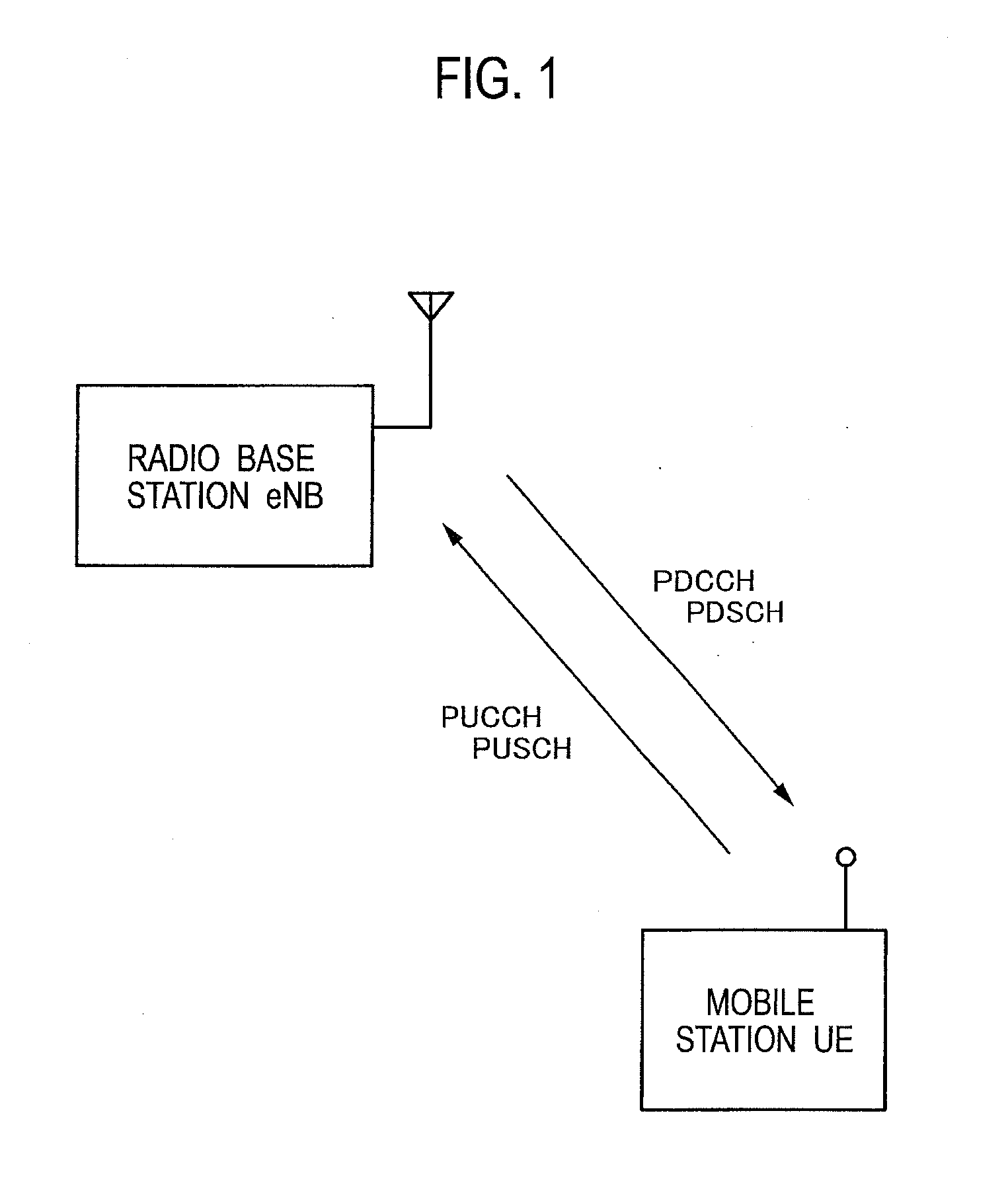
[0021]A description will now be provided for the configuration of a mobile communication system according to a first embodiment of the present invention, with reference to FIG. 1 to FIG. 6. The mobile communication system according to the present embodiment is an LTE-advanced mobile communication system.

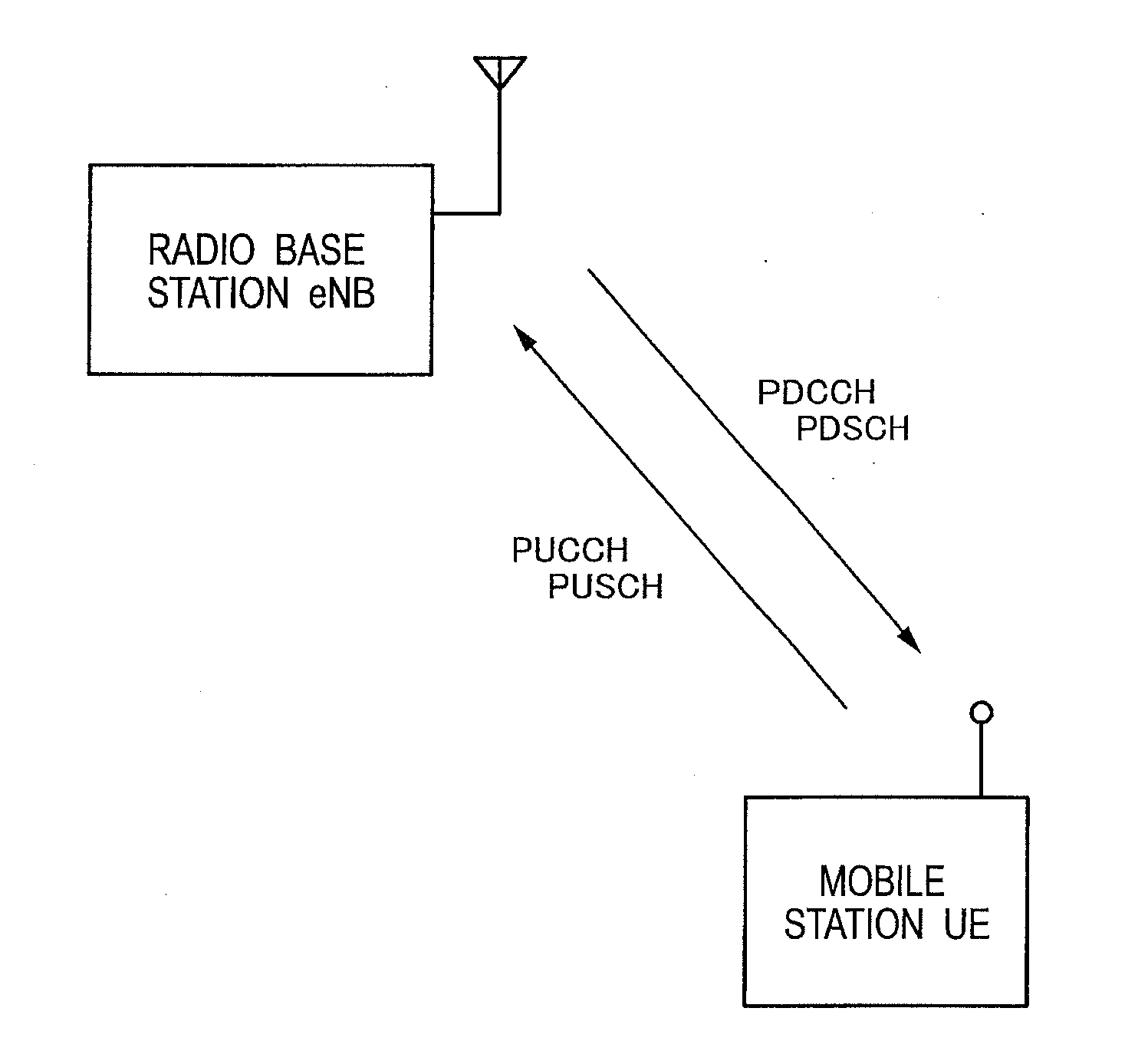
[0022]As illustrated in FIG. 1, in the mobile communication system according to the present embodiment, a mobile station UE is configured to transmit a control signal to a radio base station eNB via PUCCH (Physical Uplink Control Channel), and to transmit a data signal to the radio base station eNB via PUSCH.

[0023]Furthermore, in the mobile communication system according to the present embodiment, the radio base station eNB is configured to transmit a control signal to the mobile station UE via PDCCH, and to transmit a data signal to the mobile station UE via PDSCH.

[0024]Furthermore, as...


PUM


Abstract

A mobile communication method according to the present invention includes a step A of transmitting, by a radio base station eNB, “RRC Connection Reconfiguration” including setting information on a plurality of CCs and PDCCHs to a mobile station UE, and a step B of transmitting, by the mobile station UE, “RRC Connection Reconfiguration Complete” to the radio base station eNB using a contention-based channel in response to the received “RRC Connection Reconfiguration”.

Description

TECHNICAL FIELD[0001]The present invention relates to a mobile communication method and a mobile station.BACKGROUND ART[0002]In an LTE (Long Term Evolution)-Advanced mobile communication system, when CA (Carrier Aggregation) is performed, a mobile station UE is configured to communicate with a radio base station eNB using a plurality of “Component Carriers (CCs)” having different carrier frequencies.[0003]Here, when the CA is performed, it is possible for the radio base station eNB to limit CC, which is to be monitored in the mobile station UE among the plurality of CCs, by “PDCCH (Physical Downlink Control Channel) monitoring set”.[0004]Furthermore, when the CA is performed, it is possible for the radio base station eNB to set “CIF configuration”, which indicates a correspondence relationship between each of the plurality of CCs and CIF (Carrier Indication Field) to be set to the PDCCH, in each mobile station UE.[0005]Using the CIF, it is possible for the radio base station eNB to ...

Claims


Application Information

Patent Timeline
Patent Type & Authority Applications(United States)
IPC IPC(8): H04W72/04
CPCH04W76/04H04L5/0053H04L5/001H04L5/0098H04W76/20
Inventor IWAMURA, MIKIOMIKI, NOBUHIKOISHII, HIROYUKIUMESH, ANIL
Owner NTT DOCOMO INC
Learn More