TCP communication scheme

a communication scheme and vpn technology, applied in the field of tcp communication schemes, can solve the problems of high cost in the case of extension of the vpn section, and achieve the effects of preventing direct attacks from hackers, free choice, and reducing the implementation cos

Inactive Publication Date: 2013-11-05
MEIDENSHA ELECTRIC MFG CO LTD
View PDF10 Cites 0 Cited by
  • Summary
  • Abstract
  • Description
  • Claims
  • Application Information

AI Technical Summary

Benefits of technology

[0021]The present invention brings an advantage of allowing safe communication through communication paths close to terminals, and making a device invisible on a network because of no allocation of IP address so that direct attacks from hackers are prevented. Moreover, the present invention brings an advantage of making it unnecessary to change the configuration and setting of the network, and install special-purpose software in the terminals, and change applications in the terminals because of independency from applications. Moreover, the present invention brings an advantage of allowing coexistence with other communication protocols without affecting existing communication, and allowing free choice and extension of functions to be added.
[0022]Moreover, the present invention brings an advantage of: making it unnecessary to change the configuration and setting of the network, and using an existing standard protocol stack, and thereby reducing the implementing cost; preventing a communication band from being consumed unnecessarily, because of completion within the standard TCP connection procedure; and preventing TCP connection with unauthorized terminals, and thereby preventing computer resources from being consumed by malicious attacks. Moreover, the present invention brings an advantage of: making it possible to achieve the object in cases where the first and second relay devices are compatible with the TCP options by default, or even in cases where they are incompatible with the TCP options; and making it unnecessary to use an additional TCP port number.

Problems solved by technology

(a) Communication outside of the VPN section allows free intrusion and is therefore unsafe.
This leads to a high cost in case of arrangement that the VPN section is extended close to the terminals.

Method used


Image

  • TCP communication scheme
  • TCP communication scheme
  • TCP communication scheme

Examples


embodiment 1

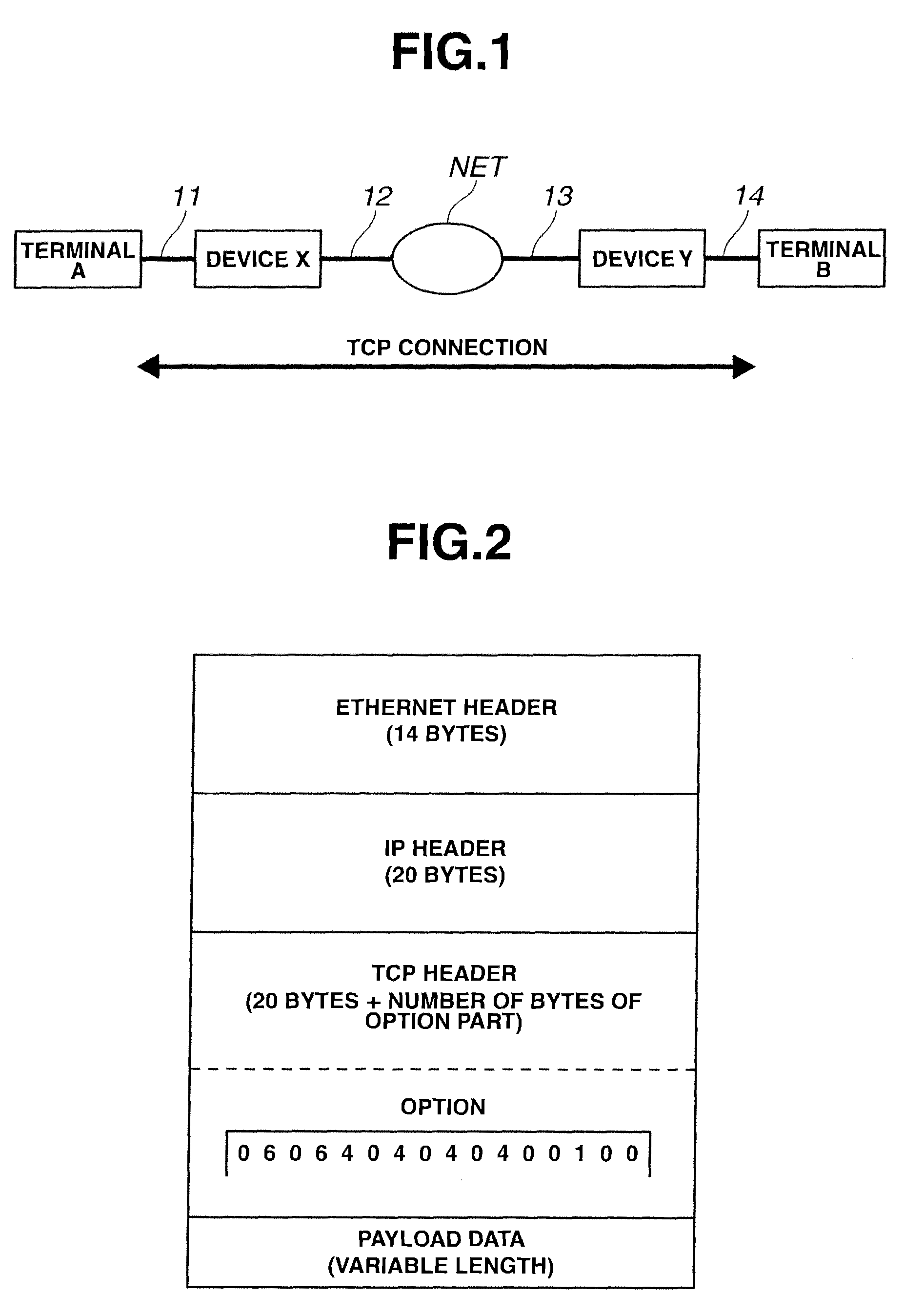
[0042]FIG. 1 is a network configuration diagram showing a TCP communication scheme according to an embodiment 1. In FIG. 1, terminals A, B are endpoint terminals located on opposite ends of TCP communication. Terminals A, B are connected to relay devices X, Y through transmission lines 11, 14, respectively. Relay devices X, Y are connected to a network NET through transmission lines 12, 13, respectively.

[0043]Relay devices X, Y are provided and inserted in a section between terminals A, B between which communication has been made previously. Relay devices X, Y are allocated with no IP addresses. For ease of explanation, terminals A, B are henceforth referred to as active side and passive side of TCP connection, respectively.

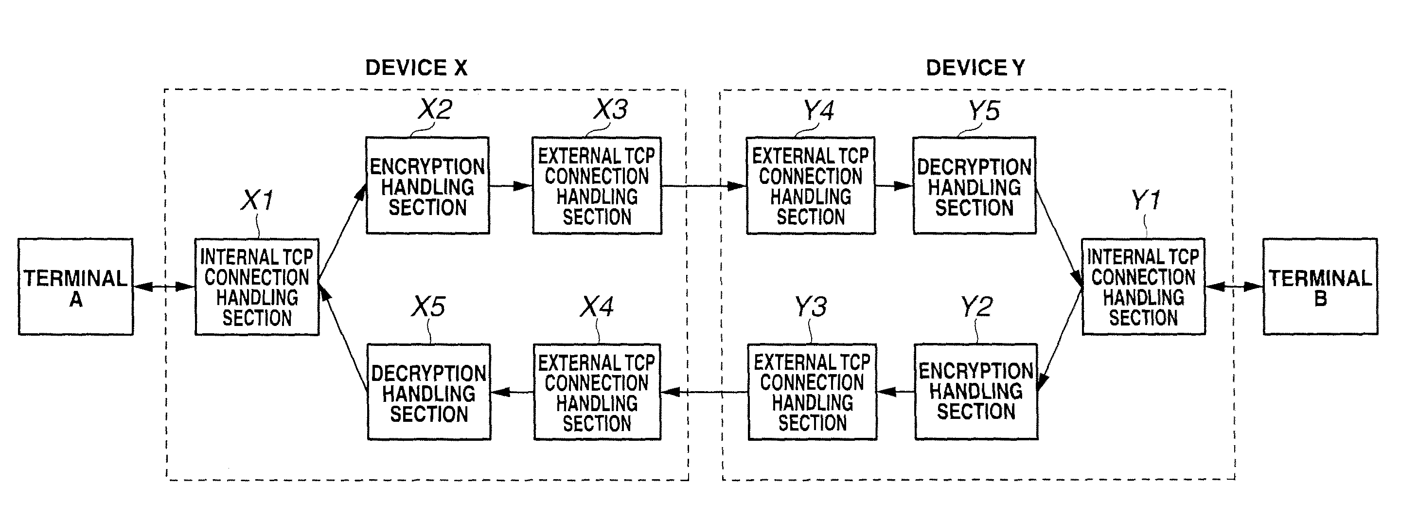
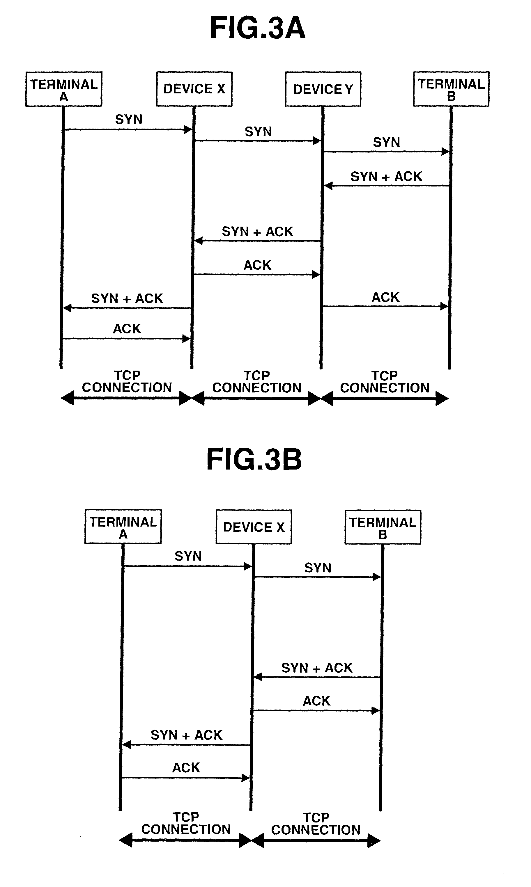
[0044]Relay devices X, Y intercept TCP connection between terminals A, B, and divide same into three TCP connections, and establish TCP communication.

[0045]The following describes operations of active-side and passive-side relay devices X, Y.

[0046](1) Operation o...

embodiment 2

[0072]An embodiment 2 employs the TCP options of type codes 06, 07. Type code 06 is “Echo (obsoleted by option 8) RFC1072”. Type code 07 is “Echo Reply (obsoleted by option 8) RFC1072”.

[0073]FIG. 11 is a diagram showing a sequence in standard mode of use of the TCP options of type codes 06 and 07. By definition, the TCP options of code types 06 and 07 are used for measuring a reply period in TCP congestion control. For example, when the sender device (relay device X) shown in FIG. 2 sends to the opposite target device (relay device Y) a packet in which an arbitrary number is set in type code 06, then the target device which has received the packet sends back to the sender device a packet in which the arbitrary number is set in type code 07. The sender device measures time when the packet in which the same number is set is reached, and uses it in congestion control.

[0074]Proactive information exchange is implemented by mutually sending an arbitrary number (packet) provided with a spe...

embodiment 3

[0093]An embodiment 3 employs the TCP option of type 19. Type 19 is “MD5 Signature Option RF2385”.

[0094]FIG. 15 is a diagram showing a sequence in standard mode of use of the TCP option of type 19. By definition, type 19 is an option intended for BGP (Border Gateway Protocol), which is used for signature based on MD5 hash value of the TCP segment. Every TCP segment flowing over a BGP session is added with this option for protecting the BGP session.

[0095]Embodiment 3 implements proactive information exchange by mutually sending an arbitrary number provided with a specific meaning, by using the function of the TCP option shown in FIG. 15. However, this scheme cannot be used over BGP sessions, because this scheme is in conflict with the standard usage over BGP sessions. Accordingly, this scheme is limited to sessions except BGP sessions. The following describes a case in which relay device X confirms or authorizes by the above method that relay device Y having a similar function exists...


PUM


Abstract

A TCP communication scheme which ensures safe communication up to the communication path near a terminal and eliminates direct attacks from hackers, etc. A terminal (A) and terminal (B) are connected to a relay apparatus (X) and relay apparatus (Y), where the terminal (A) and the terminal (B) are the endpoint terminals positioned at the two ends of a TCP communication connection. The relay apparatuses (X, Y) are each connected to a network (NET). The relay apparatuses (X and Y) are provided so as to be between the terminals (A and B) which had been performing conventional TCP communication, and neither of the relay apparatuses (X and Y) have IP addresses. The relay apparatuses (X and Y) take over the TCP connection between the terminal (A) and the terminal (B), divide the connection into three TCP connections, and establish TCP communication.

Description

TECHNICAL FIELD[0001]The present invention relates to a TCP communication scheme for relay between TCP networks, to which a specific function, such as an encrypted communication function, is added.BACKGROUND OF THE INVENTION[0002]A VPN (Virtual Private Network) router is a device inserted between endpoint communication terminals, for adding a specific function to communication therebetween. The VPN router is a device provided between two networks for adding a function of encrypting communication therebetween.[0003]There are two types of VPN routers. One is an IP-VPN type for connection using a VPN network provided by a carrier. The other is an Internet VPN type for connection through the internet wherein a VPN device is inserted by a user himself. In general, the former is used as a LAN-to-LAN-connecting VPN for connecting LANs to each other as shown in FIG. 9, and the latter is used as a remote access VPN for connecting a terminal PC to a LAN as shown in FIG. 10.[0004]In FIGS. 9, 1...

Claims


Application Information

Patent Timeline
Patent Type & Authority Patents(United States)
IPC IPC(8): H04L29/06H04L12/66H04L12/70
CPCH04L63/1475H04L69/16H04L69/163H04L69/169H04L63/0272H04L63/0428
Inventor TATEISHI, YASUSHIOKURO, TATSUYANISHIBE, YASUNORIHABUTSU, TAKASHI
Owner MEIDENSHA ELECTRIC MFG CO LTD
Why Eureka
Try Eureka