Rotation detection apparatus

a detection apparatus and rotating technology, applied in the direction of dynamo-electric components, instruments, electrical/magnetically converting sensor outputs, etc., can solve the problems of achieve the effect of redundancy without increasing the size and cost of the rotation detection apparatus

Active Publication Date: 2022-03-03
PROTERIAL LTD
View PDF17 Cites 0 Cited by
  • Summary
  • Abstract
  • Description
  • Claims
  • Application Information

AI Technical Summary

Benefits of technology

[0012]According to the present invention, redundancy in the rotation detection apparatus can be achieved without increasing the size and cost of the rotation detection apparatus.

Problems solved by technology

However, the addition or enlargement of magnets may cause an increase in size and cost of the rotation detection apparatus.

Method used


Image

  • Rotation detection apparatus
  • Rotation detection apparatus
  • Rotation detection apparatus

Examples


Embodiment Construction

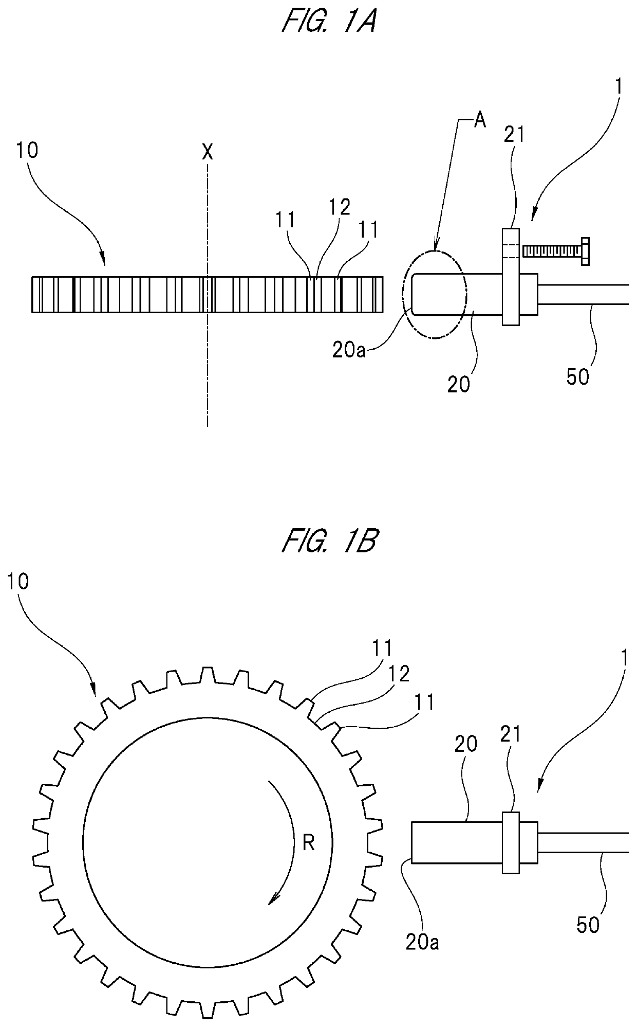
[0021]Hereinafter, a rotation detection apparatus according to one embodiment will be described in detail with reference to the drawings. Application of the rotation detection apparatus according to the present embodiment is not particularly limited, but is suitable for use as a wheel speed sensor constituting an ABS device (anti-lock braking device) or a traction control device installed in a vehicle such as an automobile.

[0022]As shown in FIGS. 1A and 1B, a rotation detection apparatus 1 according to the present embodiment is arranged in a vicinity of a gear 10 that is rotated together with a wheel, and is configured to detect a rotation state of the gear 10 based on a magnetic field change that occurs as the gear 10 is rotated. In other words, the gear 10 corresponds to an object-to-be-detected in the present invention.

[0023]The gear 10 as the object-to-be-detected is formed into a disk shape by a magnetic material. In addition, a convex portion 11 and a concave portion 12 are al...


PUM


Abstract

The present invention relates to a rotation detection apparatus configured to detect a rotation state of a gear based on a magnetic field change that occurs as the gear is rotated. The rotation detection apparatus includes: a first sensor portion and a second sensor portion each having a magnetic detection element and a covering member configured to cover the magnetic detection element; one permanent magnet arranged between the first sensor portion and the second sensor portion; and a housing portion configured to accommodate the first sensor portion, the second sensor portion and the permanent magnet.

Description

CROSS-REFERENCE TO RELATED APPLICATION[0001]The present application claims priority from Japanese Patent Application No. 2020-145315 filed on Aug. 31, 2020, the content of which is hereby incorporated by reference into this application.TECHNICAL FIELD OF THE INVENTION[0002]The present invention relates to a rotation detection apparatus configured to detect a rotation state of an object-to-be-detected based on a magnetic field change that occurs as the object-to-be-detected is rotated.BACKGROUND OF THE INVENTION[0003]An example of a rotation detection apparatus as described above is disclosed in Japanese Patent Application Laid-Open Publication No. 2015-133377 (Patent Document 1). The rotation detection apparatus disclosed in Patent Document 1 comprises a detection portion having a built-in magnetic detection element (MR element) and a built-in magnet. The detection portion is arranged so as to face an object-to-be-detected (gear made of a magnetic body). Specifically, the detection ...

Claims


Application Information

Patent Timeline
Patent Type & Authority Applications(United States)
IPC IPC(8): G01D5/14H02K11/215
CPCG01D5/14G01B7/30H02K11/215G01P3/488G01D5/147G01D11/245G01D5/2451
Inventor TOMITA, KAZUHIKO
Owner PROTERIAL LTD
Why Eureka
Try Eureka