
Image forming apparatus

a technology of forming apparatus and forming head, which is applied in the direction of instruments, digital computers, computing, etc., can solve the problems of starting an output process and being unable to meet user needs, and achieve the effects of shortening the loss time, shortening the processing time, and improving convenien

Active Publication Date: 2019-07-09
SHARP KK
View PDF53 Cites 0 Cited by
  • Summary
  • Abstract
  • Description
  • Claims
  • Application Information

AI Technical Summary

Benefits of technology

[0014]The present invention has been devised in view of the above prior art problems, it is therefore an object of the present invention to provide an image forming apparatus with improved convenience in which an image output process can be implemented in conformity with user's intention.
[0015]It is another object of the present invention to provide an image forming apparatus that is improved in convenience so that preview checking work can be cancelled whenever the user wants and that makes it possible to achieve an image output process in conformity with user's intention.

Problems solved by technology

However, as in the technology disclosed in Patent Document 1, in the image forming apparatus having a function of displaying a preview of the images to be output to enable the user to check, it is only possible to start an output process after user's confirmation of finished images before output.
That is, there has been the problem that it is impossible to achieve an output process in conformity with the intention of the user who wants to omit checking work before output (the user who puts weight on quickness), hence it is impossible to meet user needs.

Method used


Image

  • Image forming apparatus
  • Image forming apparatus
  • Image forming apparatus

Examples


first embodiment

(The First Embodiment)

[0086]The embodiment of the present invention will hereinafter be described with reference to the accompanying drawings.

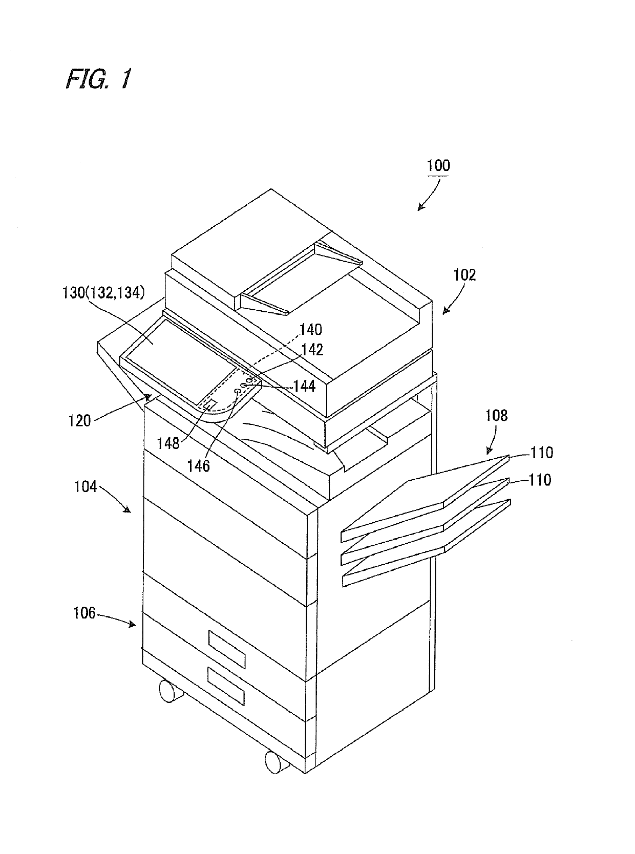
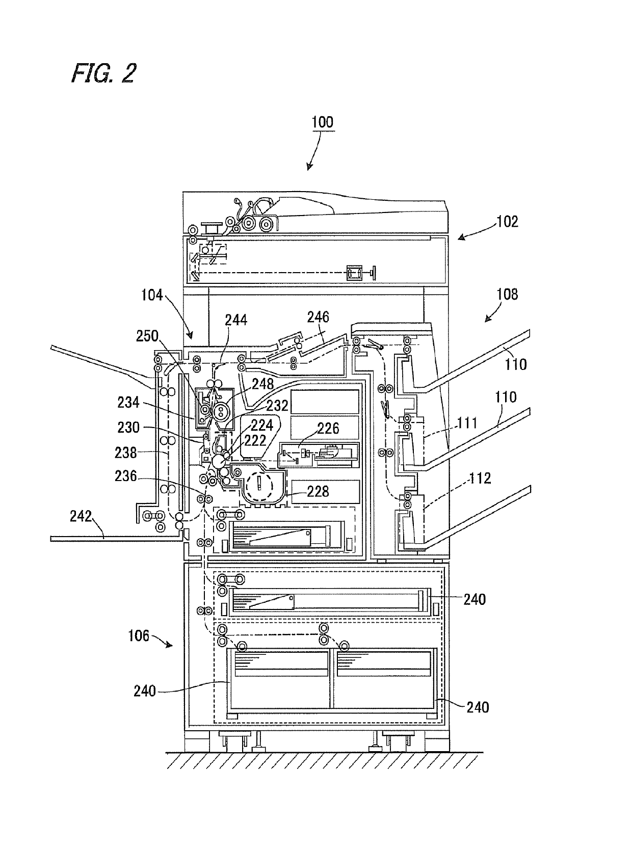
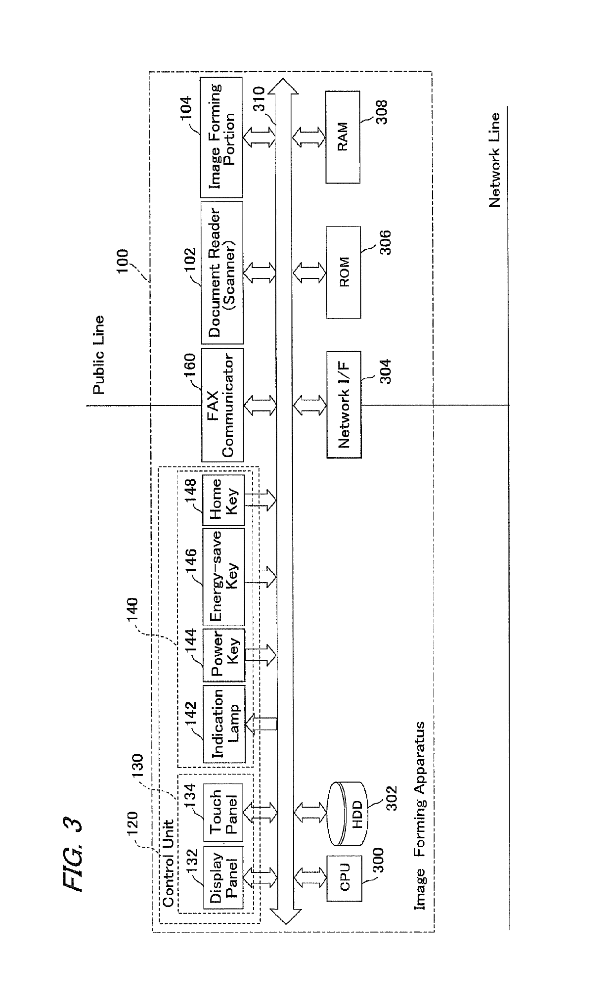
[0087]FIG. 1 is an illustrative view of one example mode of carrying out the present invention, showing an overall configuration of an image forming apparatus according to the embodiment of the present invention. FIG. 2 is an illustrative view schematically showing the internal mechanisms of the image forming apparatus. FIG. 3 is a functional block diagram showing a hardware configuration of the image forming apparatus. FIG. 4 is an illustrative view showing a preview display region on a touch panel display of the image forming apparatus. FIG. 5 is an illustrative view showing a screen example displayed on the touch panel display. FIG. 6 is an illustrative view showing a state where the preview region being displayed on the touch panel display is modified.

[0088]An image forming apparatus 100 according to the embodiment of the present invention...

second embodiment

(The Second Embodiment)

[0304]The second embodiment of the present invention will be described with reference to FIGS. 26 to 41. Since the second embodiment is different from the first embodiment in the configuration of the control unit-side controller only, description will be made focusing on the different points of the control unit-side controller. Further, in the following description, the same components as those in the first embodiment are allotted with the same reference numerals without description.

[0305]As shown in FIG. 26, control unit-side controller 131B of the present embodiment has a preview display function for displaying multiple pages of document images in a preview representation on display panel 132, a movable display function of displaying a preview of multiple page document images in a movable manner, and an input status guiding function for displaying the input status of image data input through document reader 102 on display panel 132 to guide the user.

[0306]Co...


PUM


Abstract

An image forming apparatus includes a document reader, a storage for storing image data, an image output unit and a control unit. The control unit includes a display image generator for generating a display image, a display panel and a control unit-side controller having a function of presenting the display image based on the image data input in a preview representation and an output processing function of implementing an output process. As the output processing function, two schemes are provided: a first output scheme wherein, when image data has been input through the input unit, the images are output after displaying the images to be output in a preview representation on a display panel, and a second output scheme wherein, when image data has been input through the input unit, the image is directly output without displaying the image to be output in a preview representation on the display panel.

Description

[0001]Notice: More than one reissue application has been filed for the reissue of U.S. Pat. No. 8,582,131. The reissue applications are application Ser. Nos. 15 / 202,768 (the present application) and 15 / 202,837, both of which are reissue applications of U.S. Pat. No. 8,582,131. Application Ser. No. 15 / 202,837 is a continuation reissue application of application Ser. No. 15 / 202,768 (the present application). [0002]This Nonprovisional application claims priority under 35 U.S.C. §119 (a) on Patent Application No. 2010-238890 filed in Japan on 25 Oct. 2010 and Patent Application No. 2010-239319 filed in Japan on 26 Oct. 2010, the entire contents of which are hereby incorporated by reference.BACKGROUND OF THE INVENTION[0003](1) Field of the Invention[0004]The present invention relates to an image forming apparatus such as a copier, printer, facsimile machine or the like, in particular, relating to an image forming apparatus equipped with an image display control device capable of displayi...

Claims


Application Information

Patent Timeline
Patent Type & Authority Patents(United States)
IPC IPC(8): G06F15/00H04N1/00
CPCH04N1/00411H04N1/00424H04N1/00427H04N1/00448H04N1/00458H04N1/00469H04N1/00474H04N1/00482H04N1/00503H04N2201/0094H04N2201/3288
Inventor YOSHIDA, MAYUKOTOHKI, SHINSAKU
Owner SHARP KK
Learn More