Valve, layer structure comprising a first and a second valve, micropump and method of producing a valve

a layer structure and valve technology, applied in the field of valves, layer structures and micropumps, can solve the problems of not meeting the requirements of piezo actuators, piezo actuators with hard-hard sealings that cannot be driven (opened and closed) by piezo actuators, and the size of 300 m of conventional hard-soft sealings cannot be compressed, so as to achieve faster response time, short opening/closing cycles, and improved sealing characteristics

Inactive Publication Date: 2013-03-21
FRAUNHOFER GESELLSCHAFT ZUR FOERDERUNG DER ANGEWANDTEN FORSCHUNG EV
View PDF0 Cites 21 Cited by
  • Summary
  • Abstract
  • Description
  • Claims
  • Application Information

AI Technical Summary

Benefits of technology

[0017]The present invention is based on the further finding that piezo actuators, even as membrane transducers or as piezo stacks, typically only have a technically usable stroke of some μm to some 10 μm. Therefore, conventional hard-soft-sealings with uncompressed dimensions of 300 μm cannot be driven (opened and closed) by piezo actuators. On the other hand, piezo actuators with hard-hard-sealings do not provide sufficient sealing. To implement active piezo valves with soft-sealing or hard-soft-sealing, the uncompressed dimension of the sealing structure and also the valve stroke resulting therefore may not be too large, or in other words, should be as small as possible. The same applies, for example, for peristaltic micro pumps with active valves. By providing a sealing structure with an uncompressed dimension as small as possible, for example, on a valve seat or the membrane arranged opposite to the valve seat, it is possible that the piezo actuator can open and reliably close the valve. In other words, embodiments of the present invention finally allow to provide completely sealing active valves actuated by piezo drive means or similar drive means with small strokes.
[0028]Compared to valve designs based on semiconductor materials and production processes (including embodiments of the valve comprising semiconductor materials), embodiments of the valve and of the method for producing same based on metal or metal layer structures have cost advantages with regard to the material and the production processes, because metal foils with a height or thickness of less than 500 μm can be provided at comparable low costs and also the structuring of such metal foils or layers for forming the holes, plate structures or other structures can be cost-efficiently performed using laser ablation or etching processes. In addition, metal layers can comprise lower Young's moduli compared to semiconductor layers and, thus, can be operated, for example, at lower piezo driving voltages and / or can combine high frequency switching characteristics (switching between closed and opened states) with closed states with minimum or no leakage and open states with high cross-sectional areas in the open state.

Problems solved by technology

Valves, and in particular micro valves, with hard-hard sealings, for example, between a metal valve plate and a metal valve seat, typically do not fulfill these requirements due to the roughness of the metal or its unevenness.
Therefore, conventional hard-soft-sealings with uncompressed dimensions of 300 μm cannot be driven (opened and closed) by piezo actuators.
On the other hand, piezo actuators with hard-hard-sealings do not provide sufficient sealing.

Method used


Image

  • Valve, layer structure comprising a first and a second valve, micropump and method of producing a valve
  • Valve, layer structure comprising a first and a second valve, micropump and method of producing a valve
  • Valve, layer structure comprising a first and a second valve, micropump and method of producing a valve

Examples


first embodiment

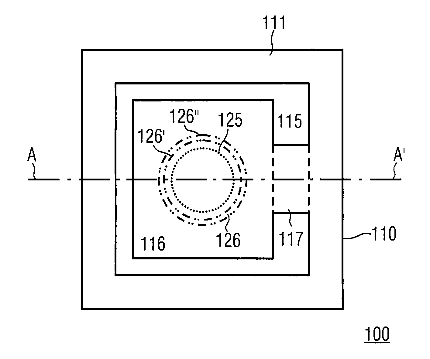
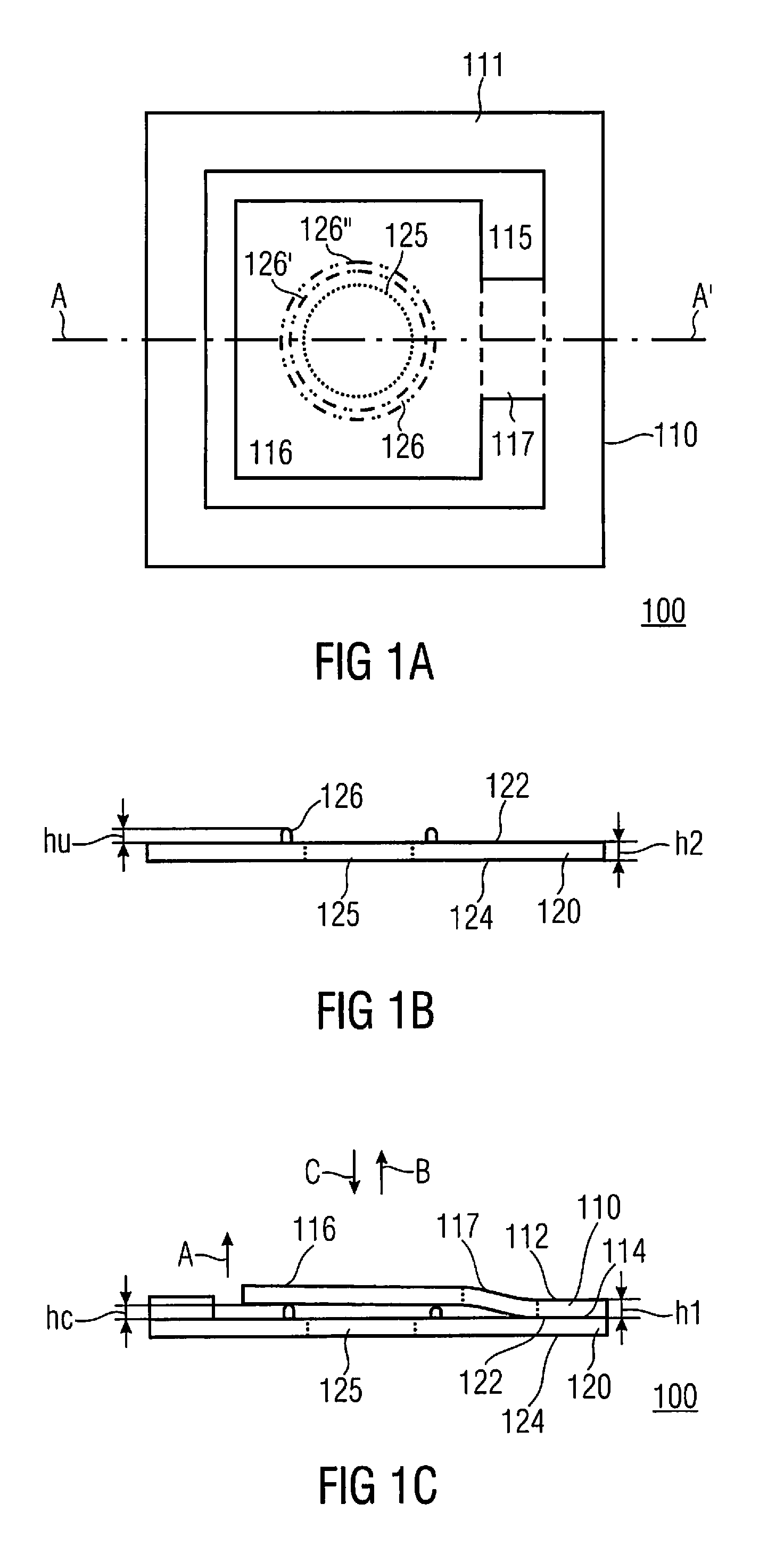
[0042]In the following a passive micro check valve, also referred to as “micro check valve” or “valve”, will be described based on FIGS. 1A to 1C. The valve opening is also referred to as hole or valve hole, the uncompressed dimension in compression direction is also referred to as uncompressed height and the compressed dimension in compression direction is also referred to as compressed height.

[0043]FIG. 1A shows a top view of the embodiment of a passive micro check valve 100 comprising a first metal layer 110 arranged on top of a second metal layer 120. The first metal layer 110 comprises a first surface 112 and a second surface 113 arranged opposite to the first surface. The second metal layer 120 comprises a first surface 122 and a second surface 124 opposite to the first surface 122 of the second metal layer 120. With regard to the orientation of FIG. 1C, the first surface 112 of the first metal layer 110 and the first surface 122 of the second metal layer 120 can also be refer...

embodiment 800

[0103]FIG. 8 shows a further embodiment 800 of a normally open active valve 800, comprising a base structure 120, for example, a foil or layer 120 with a first valve opening 125 and a second valve opening 425 formed within the base structure 120, a valve membrane formed by a further layer 110, the membrane forming at the same time the valve plate 116, a sealing structure 126 and a piezo drive means 452. The membrane 110 is pre-bulged, or in other words is bulged in case the piezo drive means 452 is not actuated. As can be seen from FIG. 8, the valve membrane 110 is arranged and connected to the base structure 120. Due to its pre-bulged shape the valve provides a fluid connection between the first valve opening 125 and the second valve opening 425 in a non-actuated state. The sealing structure 126 is arranged on a surface of the valve plate 116 respectively membrane 110 facing towards the first valve opening 125 and the second valve opening 425 and opposed to both. The piezo drive me...


PUM

PropertyMeasurementUnit
uncompressed heightaaaaaaaaaa
heightaaaaaaaaaa
thicknessaaaaaaaaaa

Abstract

A valve, including a valve opening and a valve plate arranged to seal the valve opening in a closed state by means of compressing a sealing structure is provided, wherein the sealing structure includes an uncompressed dimension in a compression direction of less than 100 μm.

Description

CROSS-REFERENCE TO RELATED APPLICATIONS[0001]This application is a continuation of copending International Application No. PCT / EP2010 / 052842, filed Mar. 5, 2010, which is incorporated herein by reference in its entirety.BACKGROUND OF THE INVENTION[0002]The present invention relates to valves, layer structures and micropumps comprising such valves and methods for producing such valves.[0003]One known technology for producing passive micro check valves is to structure silicon substrates to define a valve seat and a valve flap of a passive micro check valve. Other known technologies for producing micro check valves comprise structuring metal foils or polymeric foils to define channel and flap structures for micro check valves.[0004]Brian K. Paul and Tyson Terhaar describe in “Comparison of Two Passive Microvalve Designs for Microlamination Architectures”, J. Micromech. Microeng. 10 (2000), pages 15 to 20, a microflapper valve. The microflapper valve design consists of two laminae that ...

Claims


Application Information

Patent Timeline
Patent Type & Authority Applications(United States)
IPC IPC(8): F16K1/42B21D51/16
CPCF04B43/043F16K99/0001F16K99/0015Y10T29/49405F16K2099/008F16K2099/0094F16K99/0048Y10T137/85978F04B43/14
Inventor HERZ, MARKUSRICHTER, MARTINWACKERLE, MARTIN
Owner FRAUNHOFER GESELLSCHAFT ZUR FOERDERUNG DER ANGEWANDTEN FORSCHUNG EV
Why Eureka
Try Eureka