
Printing transferable components using microstructured elastomeric surfaces with pressure modulated reversible adhesion

a technology of elastomeric surfaces and transferable components, which is applied in the direction of dough shaping, manufacturing tools, food shaping, etc., can solve the problem of insufficient mechanical deformation of second pressur

Active Publication Date: 2013-03-21
THE BOARD OF TRUSTEES OF THE UNIV OF ILLINOIS +1
View PDF5 Cites 173 Cited by
  • Summary
  • Abstract
  • Description
  • Claims
  • Application Information

AI Technical Summary

Benefits of technology

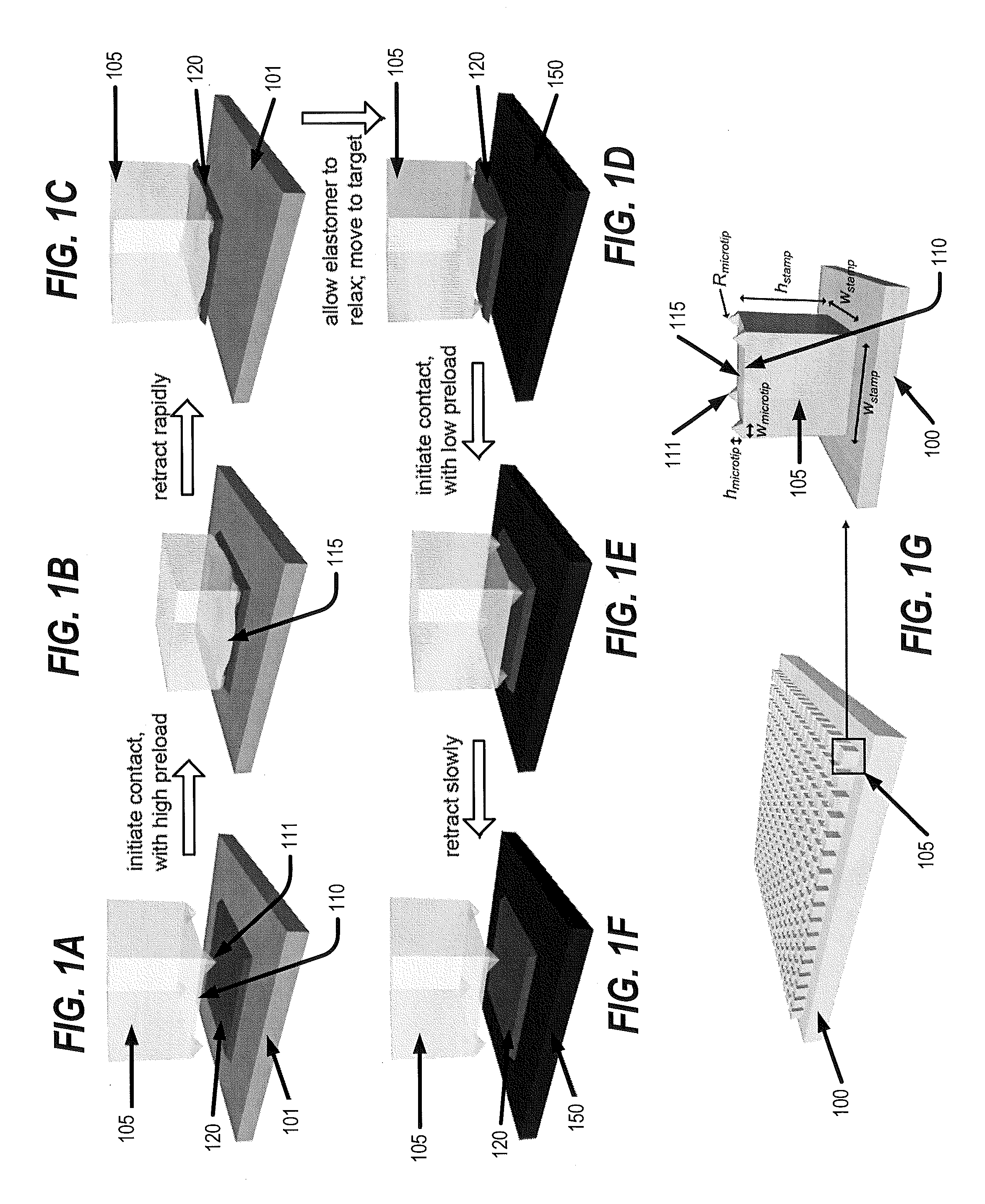
The patent describes a method for making a component with attached relief features. The method involves using a stamp to create the component, then pressing the stamp with a second pressure to compress the relief features without collapsing the region between the post and the component. The stamp is then retracted at a slower speed to delaminate the component from the donor substrate and adhere it to the receiving substrate. The technical effect of the method is the ability to make a component with good relief features attached.

Problems solved by technology

In some embodiments, the second pressure is insufficient to mechanically deform the region of the post between the relief features to contact the component.

Method used


Image

  • Printing transferable components using microstructured elastomeric surfaces with pressure modulated reversible adhesion
  • Printing transferable components using microstructured elastomeric surfaces with pressure modulated reversible adhesion
  • Printing transferable components using microstructured elastomeric surfaces with pressure modulated reversible adhesion

Examples


Embodiment Construction

[0053]The present invention now will be described more fully hereinafter with reference to the accompanying drawings, in which embodiments of the invention are shown. However, this invention should not be construed as limited to the embodiments set forth herein. Rather, these embodiments are provided so that this disclosure will be thorough and complete, and will fully convey the scope of the invention to those skilled in the art. In the drawings, the thickness of layers and regions are exaggerated for clarity. Like numbers refer to like elements throughout.

[0054]Unless otherwise defined, all terms used in disclosing embodiments of the invention, including technical and scientific terms, have the same meaning as commonly understood by one of ordinary skill in the art to which this invention belongs, and are not necessarily limited to the specific definitions known at the time of the present invention being described. Accordingly, these terms can include equivalent terms that are cre...


PUM

PropertyMeasurementUnit
Forceaaaaaaaaaa
Speedaaaaaaaaaa
Speedaaaaaaaaaa

Abstract

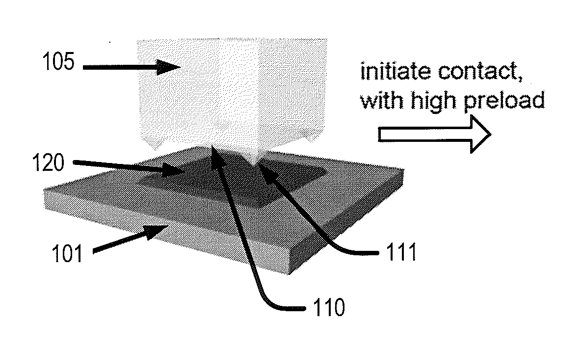
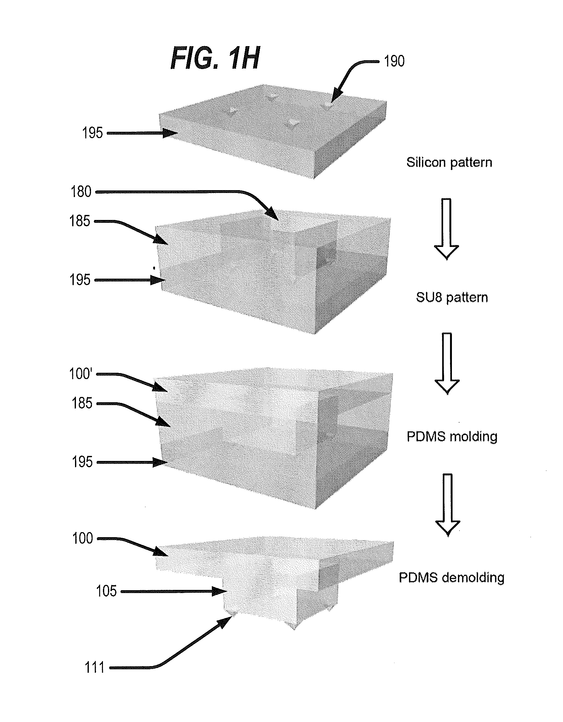
In a method of printing a transferable component, a stamp including an elastomeric post having three-dimensional relief features protruding from a surface thereof is pressed against a component on a donor substrate with a first pressure that is sufficient to mechanically deform the relief features and a region of the post between the relief features to contact the component over a first contact area. The stamp is retracted from the donor substrate such that the component is adhered to the stamp. The stamp including the component adhered thereto is pressed against a receiving substrate with a second pressure that is less than the first pressure to contact the component over a second contact area that is smaller than the first contact area. The stamp is then retracted from the receiving substrate to delaminate the component from the stamp and print the component onto the receiving substrate. Related apparatus and stamps are also discussed.

Description

RELATED APPLICATIONS[0001]This application is related to U.S. patent application Ser. No. 11 / 423,192 filed Jun. 9, 2006, and U.S. patent application Publication Ser. No. 12 / 621,804, filed Nov. 19, 2009, the disclosures of which are specifically incorporated by reference to the extent not inconsistent herewith.STATEMENT REGARDING FEDERALLY SPONSORED RESEARCH OR DEVELOPMENT[0002]This invention was made, at least in part, with United States governmental support by a National Security Science and Engineering Faculty Fellowship and the U.S. Department of Energy, Division of Materials Sciences under Award No. DEFG02-91ER45439. The United States Government has certain rights in this invention.BACKGROUND OF THE INVENTION[0003]Semiconductor chip or die automated assembly equipments typically rely on the use of vacuum operated placement heads often referred to as vacuum grippers or pick-and-place tools. In their simplest embodiment, these placement heads typically consist of an open ended cyl...

Claims


Application Information

Patent Timeline
IPC IPC(8): B29C59/02
CPCH01L25/50H01L2224/83192H01L2224/32145H01L23/4821H01L2221/68368H01L2221/68381H01L2224/95001H01L21/6835H01L2221/68363B41F16/006B81C1/00373B32B37/025B32B41/00B32B2457/14H01L21/67132B32B9/005B32B37/16B32B2313/00B41F16/00H01L21/67144
Inventor MENARD, ETIENNEROGERS, JOHN A.KIM, SEOKCARLSON, ANDREW
Owner THE BOARD OF TRUSTEES OF THE UNIV OF ILLINOIS
Learn More