Receiving apparatus

a technology of receiving apparatus and antenna, which is applied in the field of receiving apparatus, can solve problems such as the difficulty of mounting two antennas, and achieve the effect of improving the correlation coefficient of antennas and realizing features

Active Publication Date: 2012-09-18
SONY SEMICON SOLUTIONS CORP
View PDF4 Cites 3 Cited by
  • Summary
  • Abstract
  • Description
  • Claims
  • Application Information

AI Technical Summary

Benefits of technology

[0011]It is desirable to provide a receiving apparatus capable of improving correlation coefficients of antennas and sufficiently realizing the features of a diversity process.
[0013]According to the embodiment of the invention, it is possible to improve the correlation coefficients of the antennas and sufficiently realize the features of the diversity process.

Problems solved by technology

In an electronic device such as a portable phone or a note-type PC, however, it is difficult to mount two antennas due to restrictions on the design or the size.

Method used


Image

  • Receiving apparatus
  • Receiving apparatus
  • Receiving apparatus

Examples


first embodiment

1. First Embodiment

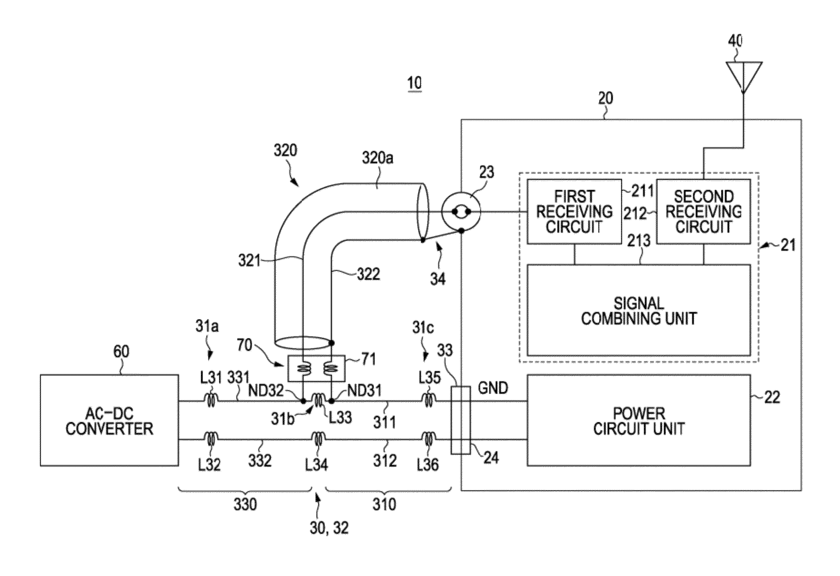
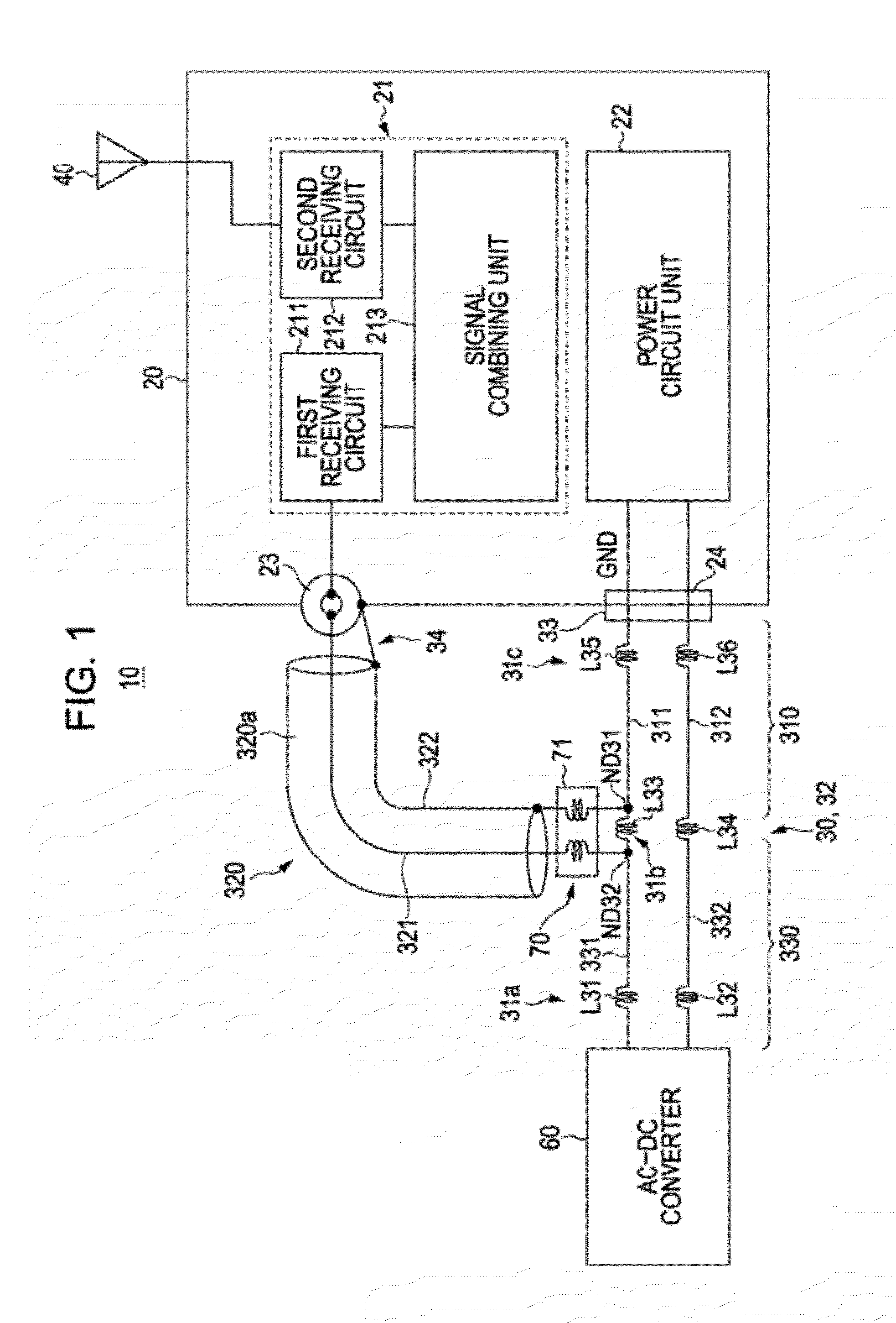
[0058]FIG. 1 is a diagram illustrating the circuit configuration of a receiving apparatus according to a first embodiment of the invention.

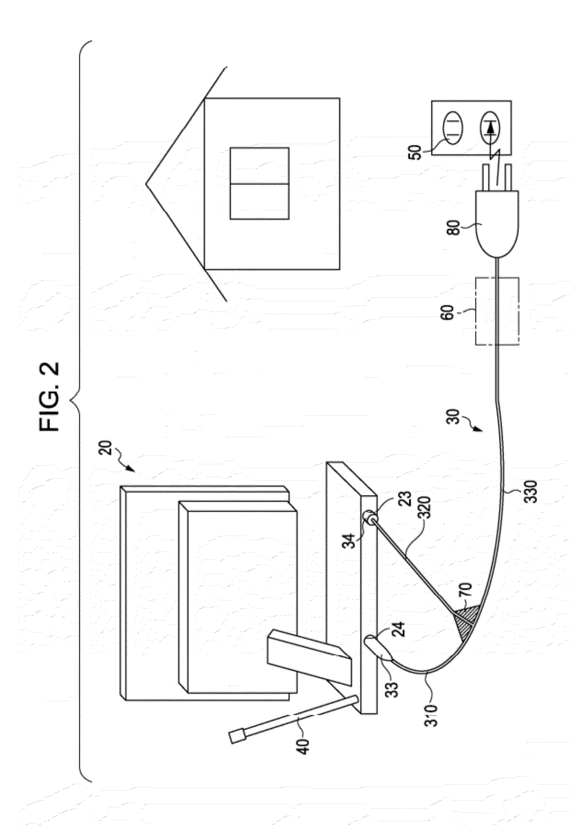
[0059]FIG. 2 is a diagram illustrating the concept of the receiving apparatus according to the embodiment of the invention.

[0060]A receiving apparatus 10 according to the first embodiment includes an electronic device 20, a power transmission cable (power supply cord) 30 transmitting power to the electronic device 20, and a first antenna 40 separate from the main body of the electronic device. In FIG. 1, Reference Numeral 50 denotes a power source socket. In FIG. 1, Reference Numeral 60 denotes an AC-DC converter.

[0061]In FIG. 2, a television receiver is shown as an example of the electronic device 20. Here, a general television receiver is exemplified for easy understanding. A compact electronic device such as a portable phone, a note-type PC, or a PND (Personal Navigation Device) with television function may be used as the el...

second embodiment

2. Second Embodiment

[0269]FIG. 30 is a diagram illustrating the circuit configuration of a receiving apparatus according to a second embodiment of the invention.

[0270]A difference between a receiving apparatus 10I according to the second embodiment and the receiving apparatus 10 according to the first embodiment is that a second antenna 32I is formed as a monopole antenna without divergence of a power transmission cable 30I.

[0271]In the power transmission cable 30I according to the second embodiment, inductors L31 and L32 formed by two parallel lines 311I and 312I and serving as a high-frequency blocking section 31a are disposed on the side of the AC-DC converter 60.

[0272]In an electronic device 20I according to the second embodiment, in order to separate the high-frequency signal caused by the power transmission cable 30I from the power, inductors L35 and L36 serving as a high-frequency blocking section 31c are formed in series on a board including the power circuit 22 connected to...

third embodiment

3. Third Embodiment

[0289]FIG. 33 is a diagram illustrating the circuit configuration of a receiving apparatus according to a third embodiment of the invention.

[0290]A difference between a receiving apparatus 10J according to the third embodiment and the receiving apparatus 10I according to the second embodiment is that a power transmission cable 30J is formed by two shield-attached lines and a braided shield portion 313 is configured as an antenna.

[0291]A signal line 312 is connected to the power circuit 22 via an inductor L36. A signal line 311 is connected to the set ground GND.

[0292]The shield portion 313 of the power transmission cable 30J is connected to the first receiving circuit 211 of the diversity processor (tuner) 21 via a matching circuit 25 and C22.

[0293]In the receiving apparatus 10J in FIG. 33, since isolation is further achieved by separating a DC circuit and an RF circuit each other physically, it is possible to reduce the influence of a power noise or the like.


PUM


Abstract

A receiving apparatus includes: an electronic device; a first antenna which is provided so as to be separate from a main body of the electronic device and receives broadcast waves; and a power transmission cable which transmits power to the electronic device. In the power transmission cable, a high-frequency blocking section is disposed on the side of a power source, and at least a part of the power transmission cable functions as a second antenna receiving a broadcast wave. The electronic device includes a diversity processor executing a diversity process on a signal received by the first antenna and a signal received by the second antenna.

Description

CROSS REFERENCE TO RELATED APPLICATIONS[0001]The present application claims priority under 35 U.S.C. §119 to Japanese Priority Patent Application JP 2009-072556, filed in the Japan Patent Office on Mar. 24, 2009, the entire contents of which are hereby incorporated by reference.BACKGROUND OF THE INVENTION[0002]1. Field of the Invention[0003]The present invention relates to a receiving apparatus capable of receiving broadcast waves.[0004]2. Description of the Related Art[0005]A digital broadcast has been initialized to satisfy demand for the effective use of frequency and a high-quality image. However, a receiving system configured to receive the digital broadcast is basically designed to receive signals through the directional Yagi antenna installed in a rooftop or a roof.[0006]In recent years, however, a tuner capable of receiving a high definition (HD) television image has also been mounted in a note-type personal computer (PC) or a compact television. Therefore, demand for viewin...

Claims


Application Information

Patent Timeline
Patent Type & Authority Patents(United States)
IPC IPC(8): H04B1/16H01Q1/24H01Q1/46H01Q3/24H04B7/08H04N5/44
CPCH01Q1/46H04B7/084H04B7/0825H04B7/0871H04B7/0831H01Q1/24H04B1/7115
Inventor YOSHINO, YOSHITAKAKOMORI, CHISATOMUKAI, KOICHI
Owner SONY SEMICON SOLUTIONS CORP
Why Eureka
Try Eureka