Wireless communication apparatus

a communication apparatus and wireless technology, applied in the direction of electrical apparatus, antenna details, antennas, etc., can solve the problems of significant difficulty in reducing the correlation between the antennas, significant difficulty in obtaining desired, and differences in antenna efficiency, so as to reduce the correlation and low cost

Inactive Publication Date: 2013-03-21
SONY MOBILE COMM INC
View PDF7 Cites 50 Cited by
  • Summary
  • Abstract
  • Description
  • Claims
  • Application Information

AI Technical Summary

Benefits of technology

[0014]The first and second electrically conductive plates form the predetermined slit therebetween to provide a function equivalent to that of a slit antenna. The interposition of such a slit antenna between the first and second electrically conductive plates reduces the correlation between the first and second antenna sections.
[0015]By effectively utilizing existing components provided in the wireless communication apparatus as the first and second electrically conductive plates, it is possible to provide a wireless communication apparatus with desired antenna characteristics at a low cost.

Problems solved by technology

For example, in a service in 700-MHz band in the United States, it is significantly difficult to reduce the correlation between the antennas.
Hence, if it is attempted to improve the correlation by varying the directivity by changing the design of one of the antennas, it is considerably difficult to obtain desired results.
However, connecting parasitic elements to the vicinity of a power feed element as in the related art described above may cause a difference in antenna efficiency.
Thus, the related art described above is not suitable for the MIMO, for which antennas with an equal antenna efficiency are ideally preferable.

Method used


Image

  • Wireless communication apparatus
  • Wireless communication apparatus
  • Wireless communication apparatus

Examples


Embodiment Construction

[0045]Embodiments of the present disclosure will be described in detail below with reference to the drawings.

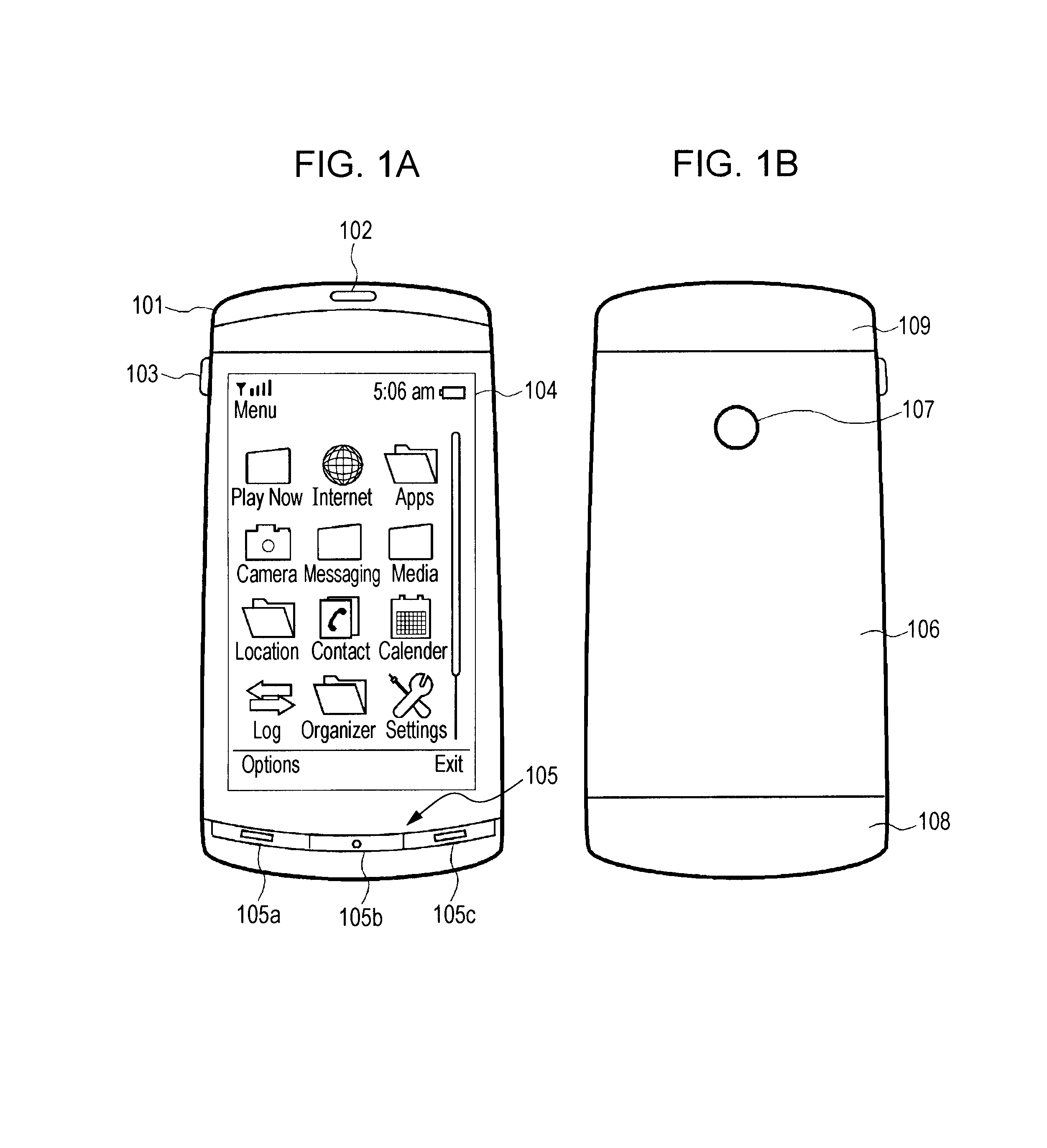
[0046]FIGS. 1(a) and 1(b) show the appearance of the front surface and the back surface, respectively, of a portable terminal, such as that called “smartphone”, serving as an example of a wireless communication apparatus according to an embodiment of the present disclosure. The portable terminal has a housing 101 having a substantially rectangular parallelepiped outer shape.

[0047]A display screen 104 of a display device such as an LCD is provided on the front surface side of the portable terminal shown in FIG. 1(a). A speaker section 102 is disposed on the upper side of the display screen 104. An operating section 105 including operating keys 105a to 105c is disposed on the lower side of the display screen 104.

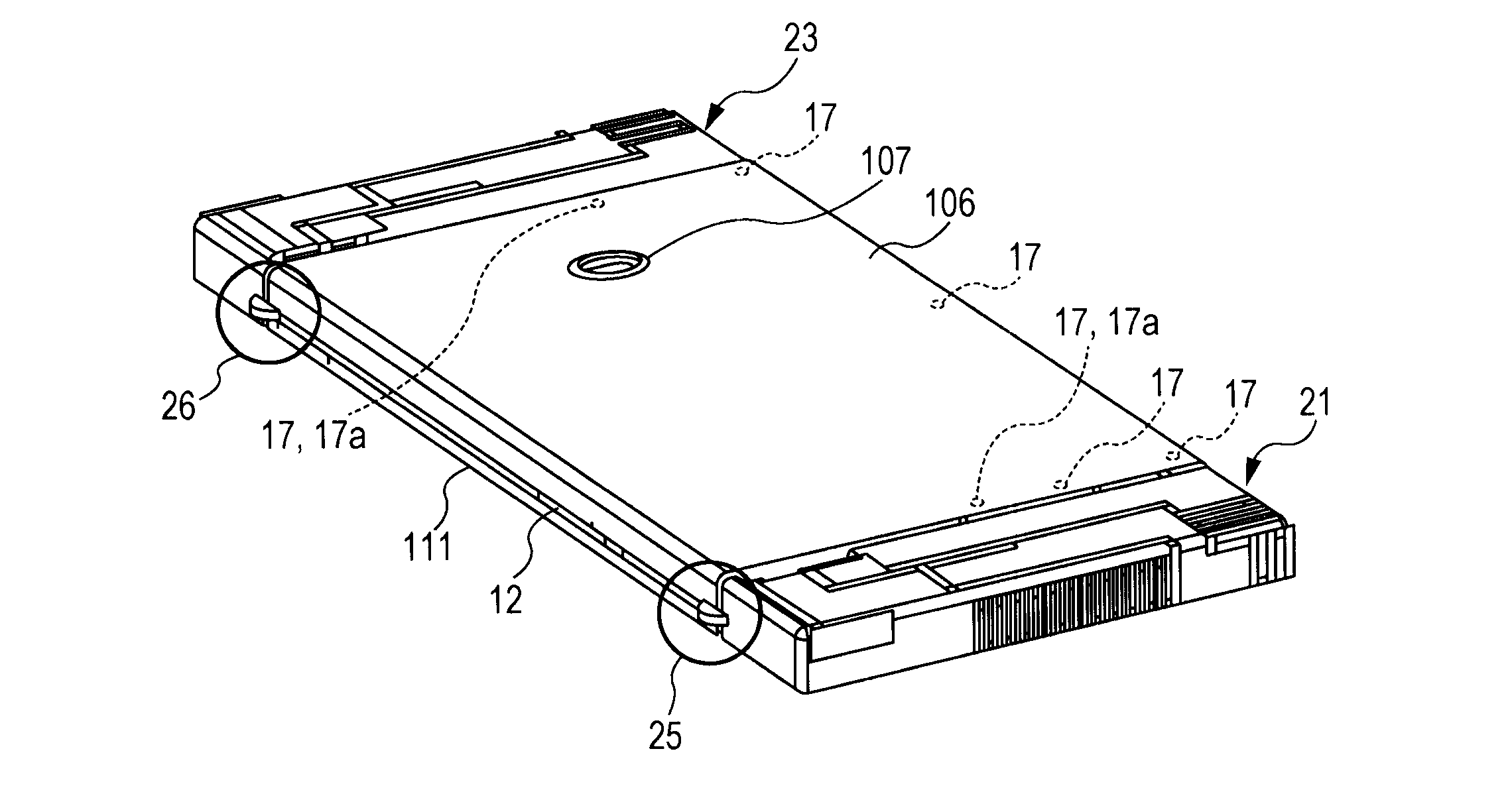
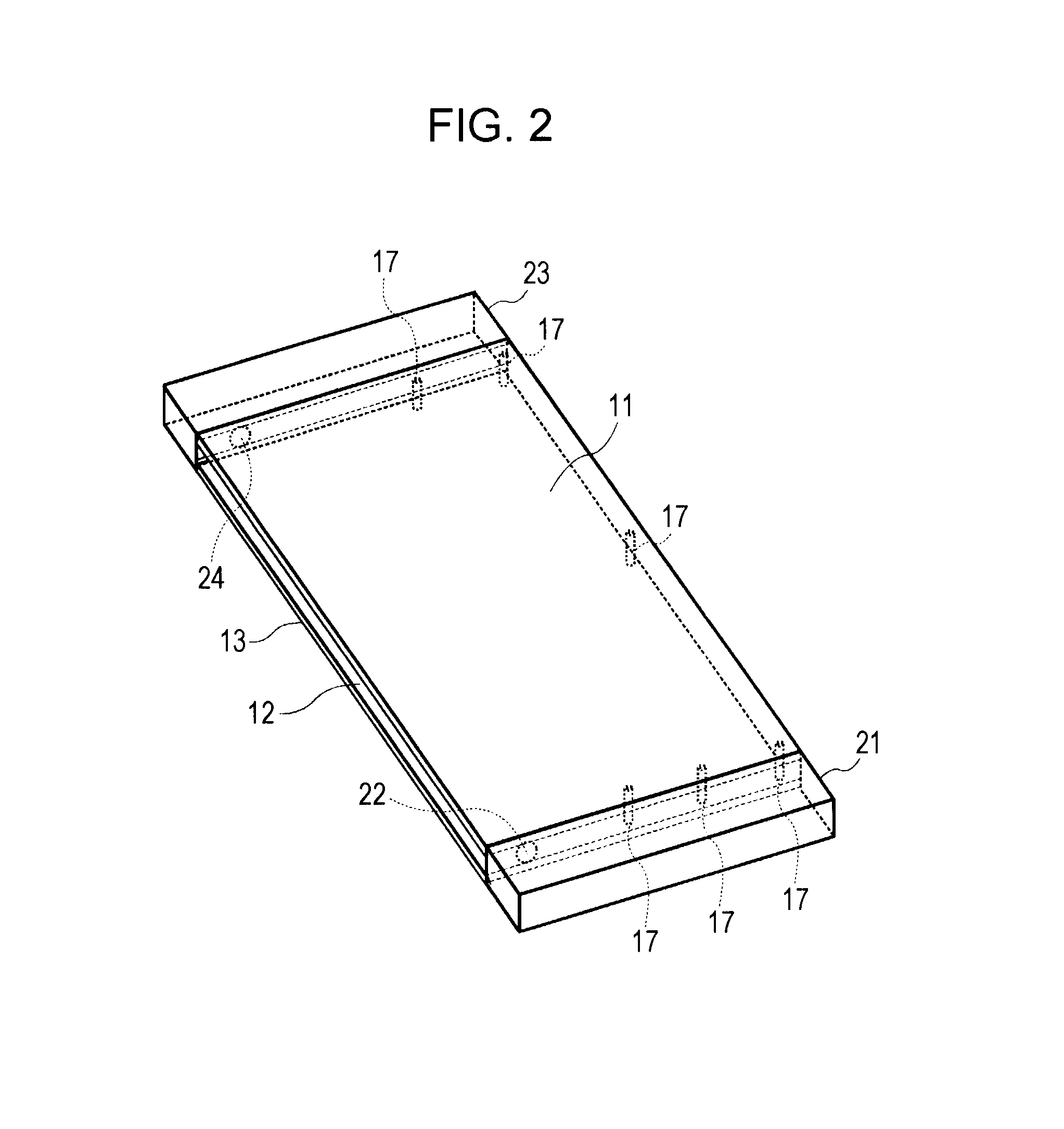
[0048]As well shown in FIG. 1(b), the portable terminal includes a main antenna section 108 serving as a first antenna section at the lower end of the portable terminal...


PUM


Abstract

A wireless communication apparatus that includes a first antenna section having a first power feed point; a second antenna section having a second power feed point; a first electrically conductive plate extending between the first antenna section and the second antenna section; a second electrically conductive plate disposed substantially in parallel with the first electrically conductive plate and extending between the first antenna section and the second antenna section; and a short-circuiting member that electrically short-circuits the first electrically conductive plate and the second electrically conductive plate to each other such that a slit is formed by a part of a periphery of the first electrically conductive plate and a part of a periphery of the second electrically conductive plate.

Description

CROSS REFERENCE TO RELATED APPLICATION[0001]The present application claims the benefit of the earlier filing date of U.S. Provisional Patent Application Ser. No. 61 / 537,109 filed on Sep. 21, 2011, the entire contents of which is incorporated herein by reference.BACKGROUND[0002]1. Field of the Disclosure[0003]The present disclosure relates to an antenna device, and relates in particular to (but is not limited to) a wireless communication apparatus that adopts a MIMO (Multi Input Multi Output) antenna device.[0004]2. Description of Related Art[0005]A service called “LTE” (Long Term Evolution) is known as one of specifications for high-speed data communication for cellular phones. When seen from a technical viewpoint for an antenna, the LTE has the following characteristics.[0006]That is, the LTE is intended for a communication system called “MIMO”, in which a plurality of antennas are used for transmission and reception to achieve high-speed data communication. A wireless communicatio...

Claims


Application Information

Patent Timeline
Patent Type & Authority Applications(United States)
IPC IPC(8): H01Q1/00
CPCH01Q1/243H01Q25/00H01Q21/28H01Q1/521
Inventor BUNGO, AKIHIRO
Owner SONY MOBILE COMM INC
Why Eureka
Try Eureka