
Formation Apparatus Using Digital Image Correlation

a technology of digital image and formation apparatus, applied in image enhancement, television systems, instruments, etc., can solve the problems of affecting the rigidity of the structure, the device cannot monitor an outdoor scene, and the strain meter is difficult to apply

Inactive Publication Date: 2013-03-21
NAT APPLIED RES LAB
View PDF8 Cites 47 Cited by
  • Summary
  • Abstract
  • Description
  • Claims
  • Application Information

AI Technical Summary

Benefits of technology

The goal of this patent is to monitor large areas with multiple cameras to measure displacement and strain. The system has the benefits of measuring the entire field, being far from the cameras, and being convenient.

Problems solved by technology

However, the device can not monitor an outdoor scene, like mountain tendency.
Although the traditional strain meter can measure strain with high accuracy, the strain meter is hard to be applied on multiple points or whole field, which may become expensive and cause problems in line layout.
A big displacement may harm rigidity of the structure.
Hence, the prior art does not fulfill all users' requests on actual use.

Method used


Image

  • Formation Apparatus Using Digital Image Correlation
  • Formation Apparatus Using Digital Image Correlation
  • Formation Apparatus Using Digital Image Correlation

Examples


Embodiment Construction

[0019]The following description of the preferred embodiment is provided to understand the features and the structures of the present disclosure.

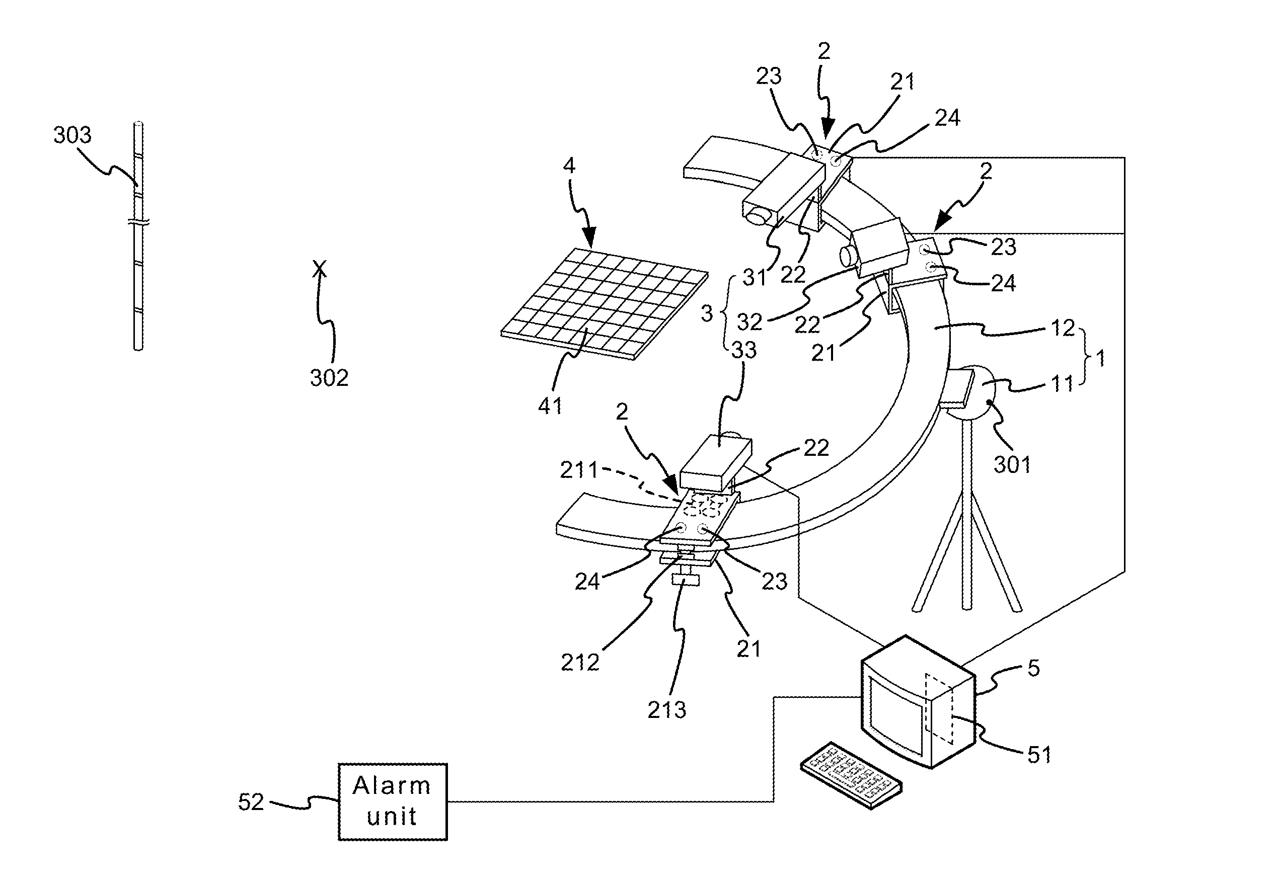
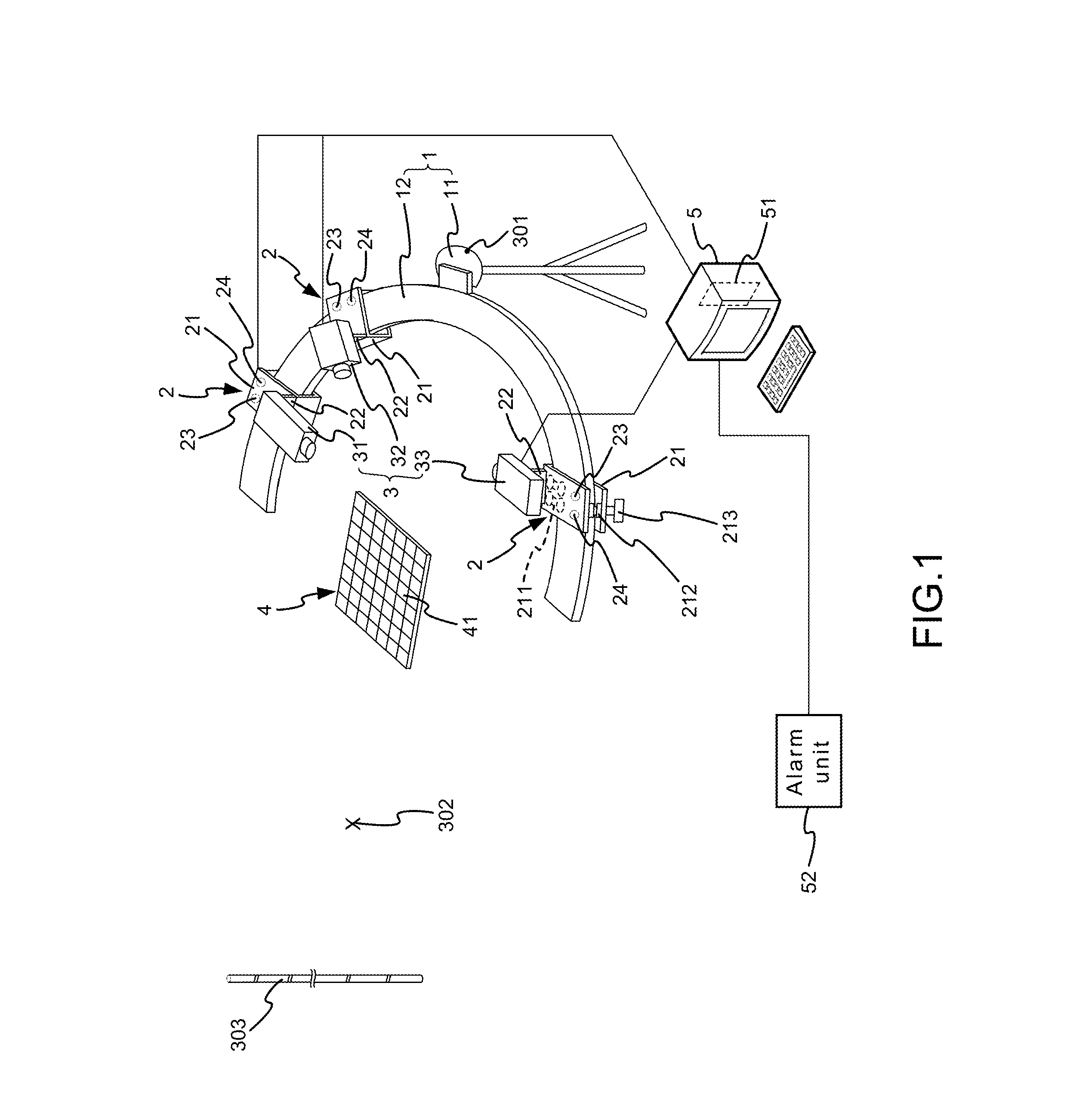
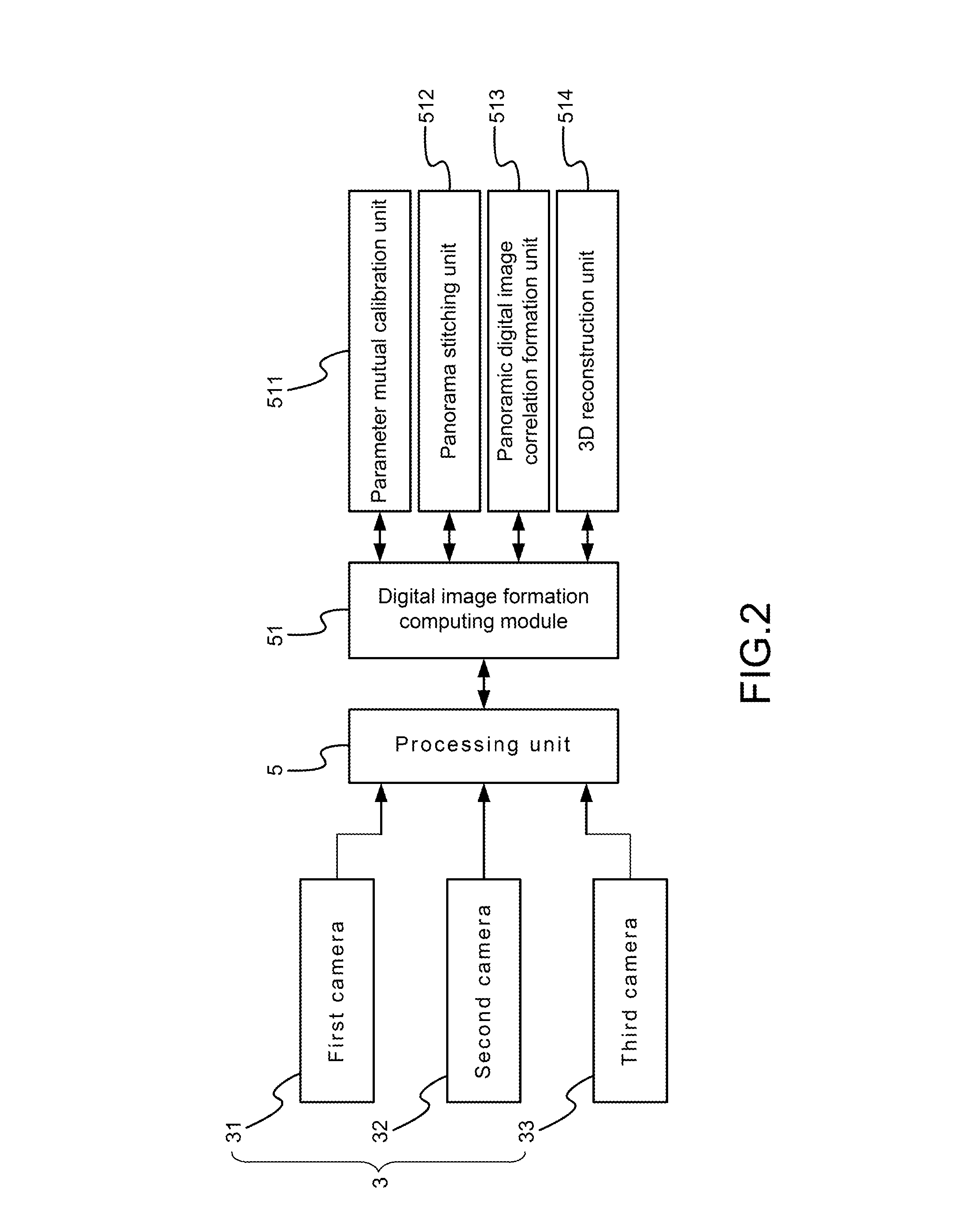
[0020]Please refer to FIG. 1 to FIG. 8, which are a perspective view showing a preferred embodiment according to the present disclosure; a view showing an image taking unit and a processing unit; a view showing a 3D strain measuring system; a first view showing a measurement of camera calibration parameters; a view showing a camera model and a projecting process; a view showing a calibrating point on a π′ plane; a second view showing the measurement of camera calibration parameters; and a view showing a panorama stitching. As shown in the figures, the present disclosure is a formation apparatus using digital image correlation, comprising a bearing unit 1, a plurality of adjusting units 2, an image taking unit 3, a calibration plate 4 and a processing unit 5.

[0021]The bearing unit 1 comprises a base 11 and a measuring track 12, where the meas...


PUM


Abstract

The present disclosure uses at least three cameras to monitor even a large-scale area. Displacement and strain are measured in a fast, convenient and effective way. The present disclosure has advantages on whole field, far distance and convenience.

Description

TECHNICAL FIELD OF THE DISCLOSURE[0001]The present disclosure relates to digital image correlation; more particularly, relates to monitoring even a large-scale area with at least three cameras for measuring displacement and strain.DESCRIPTION OF THE RELATED ART[0002]Digital image correlation was revealed in 1980s. In 1982, Peters and Ranson studied reaction of object after affected by outer force through digital images (Peters, W. H., and Ranson, W. F., 1982, “Digital image techniques on experimental stress analysis” Opt. Eng., 21(3), 427-431.). They, then, worked with other people on studying image preprocessing, value convergence and evaluation (Sutton, M. A., Wolters, W. J., et al., 1983, “Determination of displacements using an improved digital image correlation method,” Image Vision Computing, 1(3), 133-139.; Chu, T. C., Peters, W. H., Sutton, M. A., McNeil, S. R., 1985, “Application of digital image correlation to experimental mechanics,” Image Vision Computing, 25(3), 232-245...

Claims


Application Information

Patent Timeline
Patent Type & Authority Applications(United States)
IPC IPC(8): H04N13/02H04N7/18
CPCH04N13/0242H04N13/0246G06T2207/10012G01B2210/52G06T7/002G01B11/16G06T7/85H04N13/243H04N13/246
Inventor HUANG, CHI-HUNGCHEN, YUNG-HSIANGWANG, WEI-CHUNGLIAO, TAI-SHAN
Owner NAT APPLIED RES LAB
Learn More