Lighting apparatus

a technology of light-emitting devices and light-emitting devices, which is applied in the direction of light-emitting devices for light sources, transportation and packaging, lighting and heating devices, etc., can solve the problems of unsatisfactory workability and increase in the number of components, and achieve the effect of simplifying the assembling work and simple fitting

Inactive Publication Date: 2013-03-21
SHARP KK
View PDF5 Cites 14 Cited by
  • Summary
  • Abstract
  • Description
  • Claims
  • Application Information

AI Technical Summary

Benefits of technology

[0008]The present invention has been devised in view of this situation. Its object is to provide a lighting apparatus in which assembling work is simplified.
[0010]In the present invention, further provided is a light source supporting body having a locking part locking into the heat sink so as to hold the light source on the heat sink. The cover has a protruding part fitting and locking into the light source supporting body or the heat sink. In the insulating member, one end side has an inserted part inserted and locking into the heat sink, and the other end side has a connection part screwed or locked into the cap. Thus, attaching between the cover and the light source supporting body, between the light source supporting body and the heat sink plus the light source, between the heat sink and the insulating member, between the insulating member and the cap, and the like is achieved merely by simple fitting with each other. This avoids the necessity of screws and hence simplifies the assembling work.
[0014]In the present invention, the pinching part pinching the power supply part is provided in the inside of the insulating member. Thus, the power source part is fixed to the insulating member when the pinching parts merely pinch the power source part. This avoids the necessity of screws in attaching the power source part, and hence simplifies the assembling work.

Problems solved by technology

This causes complexity in the assembling work and hence causes a problem of unsatisfactory workability.
Further, a problem of increase in the number of components arises.

Method used


Image

  • Lighting apparatus
  • Lighting apparatus
  • Lighting apparatus

Examples


Embodiment Construction

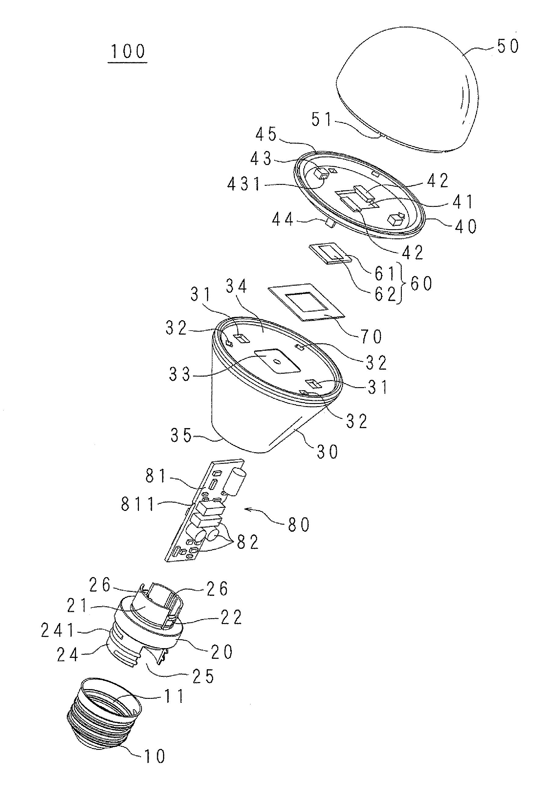
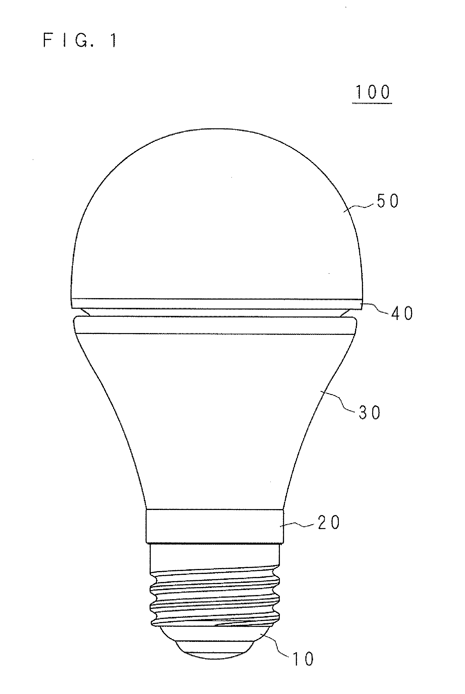
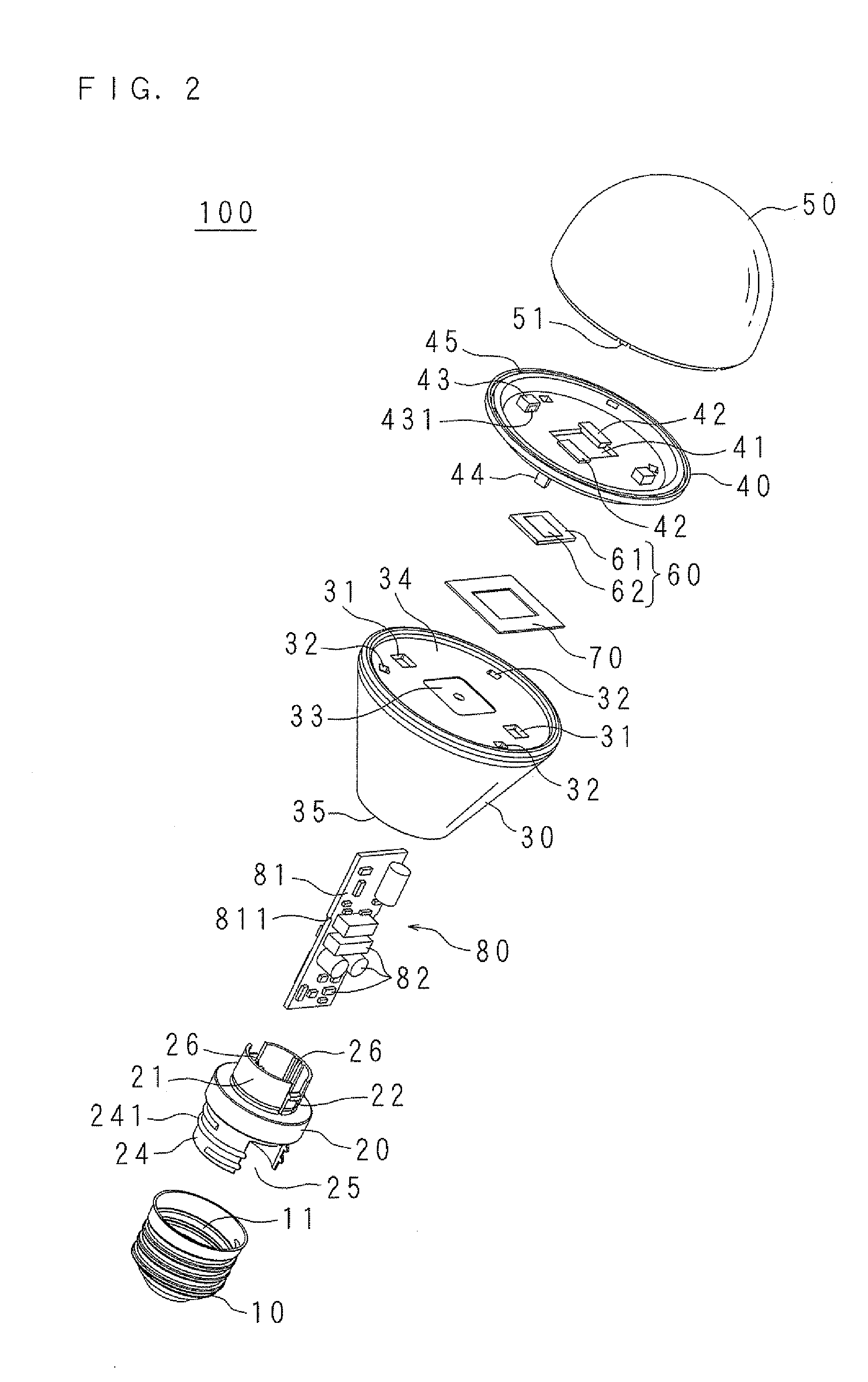
[0029]The present invention is described below with reference to the drawings illustrating an embodiment. FIG. 1 is an external appearance view of a lighting apparatus 100 according to the present embodiment. FIG. 2 is an exploded perspective view of a main part of the lighting apparatus 100 according to the present embodiment. FIG. 3 is a sectional front view of the lighting apparatus 100 according to the present embodiment. FIG. 4 is a sectional side view of the lighting apparatus 100 according to the present embodiment. The lighting apparatus 100 has the shape of an electric bulb of 40 W, 60 W, or the like.

[0030]As illustrated in FIG. 1, in the external appearance view, the lighting apparatus 100 includes: a cap 10 to be inserted into a socket in the outside so as to be electrically connected to a commercial power source; a heat sink 30 having a hollow (cylindrical) shape so as to release heat generated by the lighting apparatus 100; a cylindrical insulating member 20 linking the...


PUM


Abstract

A lighting apparatus includes: an LED module; a heat sink releasing heat generated by the LED module; a cover covering the LED module; a cap; and an insulating member located between the cap and the heat sink. Further provided is a light source supporting body having a locking part locking into the heat sink so as to hold the LED module on the heat sink. The cover has a protruding part fitting and locking into the light source supporting body or the heat sink. In the insulating member, one end side has an inserted part locking into the heat sink, and the other end side has a connection part screwed into the cap.

Description

[0001]This application is the national phase under 35 U.S.C. §371 of PCT International Application No. PCT / JP2011 / 059482 which has an International filing date of Apr. 18, 2011 and designated the United States of America.BACKGROUND[0002]1. Technical Field[0003]The present invention relates to a lighting apparatus provided with a light source and, in particular, to a lighting apparatus having the shape of an electric bulb.[0004]2. Description of Related Art[0005]In recent years, with advancement in development of high luminance light emitting diodes (LEDs), in place of light sources such as incandescent lamps and fluorescent lamps, LEDs having features of low power consumption, long life, and the like are increasingly widely used as light sources in lighting apparatuses or the like.[0006]A lighting apparatus employing as a light source a light emitting element such as an LED includes: a board on which the LED is mounted; and a heat sink releasing heat generated by the LED. For exampl...

Claims


Application Information

Patent Timeline
Patent Type & Authority Applications(United States)
IPC IPC(8): F21V29/00
CPCF21V3/00F21V19/003F21V19/004F21Y2101/02F21K9/1355F21V7/22F21V29/89F21V23/002F21V17/005F21V17/104F21V17/164F21V29/70F21V29/87F21V13/02F21K9/23F21Y2115/10F21V7/24H01L2224/48091H01L2924/00014
Inventor SHINOHARA, YUECHIGO, TAKESHIYAMAMOTO, SHOJI
Owner SHARP KK
Why Eureka
Try Eureka