Arrangement for a charger

a charger and charger body technology, applied in the direction of inductance, gas-filled discharge tubes, cathode-ray/electron beam tube circuit elements, etc., can solve the problems of receiver misplacement, inefficient charging or even worse, inaccurate signalling of the correct location, etc., to achieve accurate signalling the effect of charging and charging

Inactive Publication Date: 2013-03-28
POWERMAT TECHNOLOGIES
View PDF4 Cites 68 Cited by
  • Summary
  • Abstract
  • Description
  • Claims
  • Application Information

AI Technical Summary

Benefits of technology

[0006]The invention is based on the idea of accurately signalling the correct location for the receiver. An advantage of the method and arrangement of the invention is that the charging is efficient and that the charging begins immediately.

Problems solved by technology

If this happens, the charging is inefficient or even worse, no charging occurs.
The accurate placing becomes even more challenging when an existing surface is to be changed to a wireless charging surface without changing the original purpose of the surface.
However, this does not cause the charging to begin, because it is probable that the receiver is misplaced in relation to the transmitter, which is inside of the mat.
Moreover, current prior art wireless charging systems are not wireless in reality, because there are still wires within the user's reach.
Hence an energy transmitter element, an identification element or both that enable wireless charging in prior art solutions are still connected to the mains by a wire and therefore they do not support comprehensive wireless power transmission and charging.

Method used


Image

  • Arrangement for a charger
  • Arrangement for a charger
  • Arrangement for a charger

Examples


Embodiment Construction

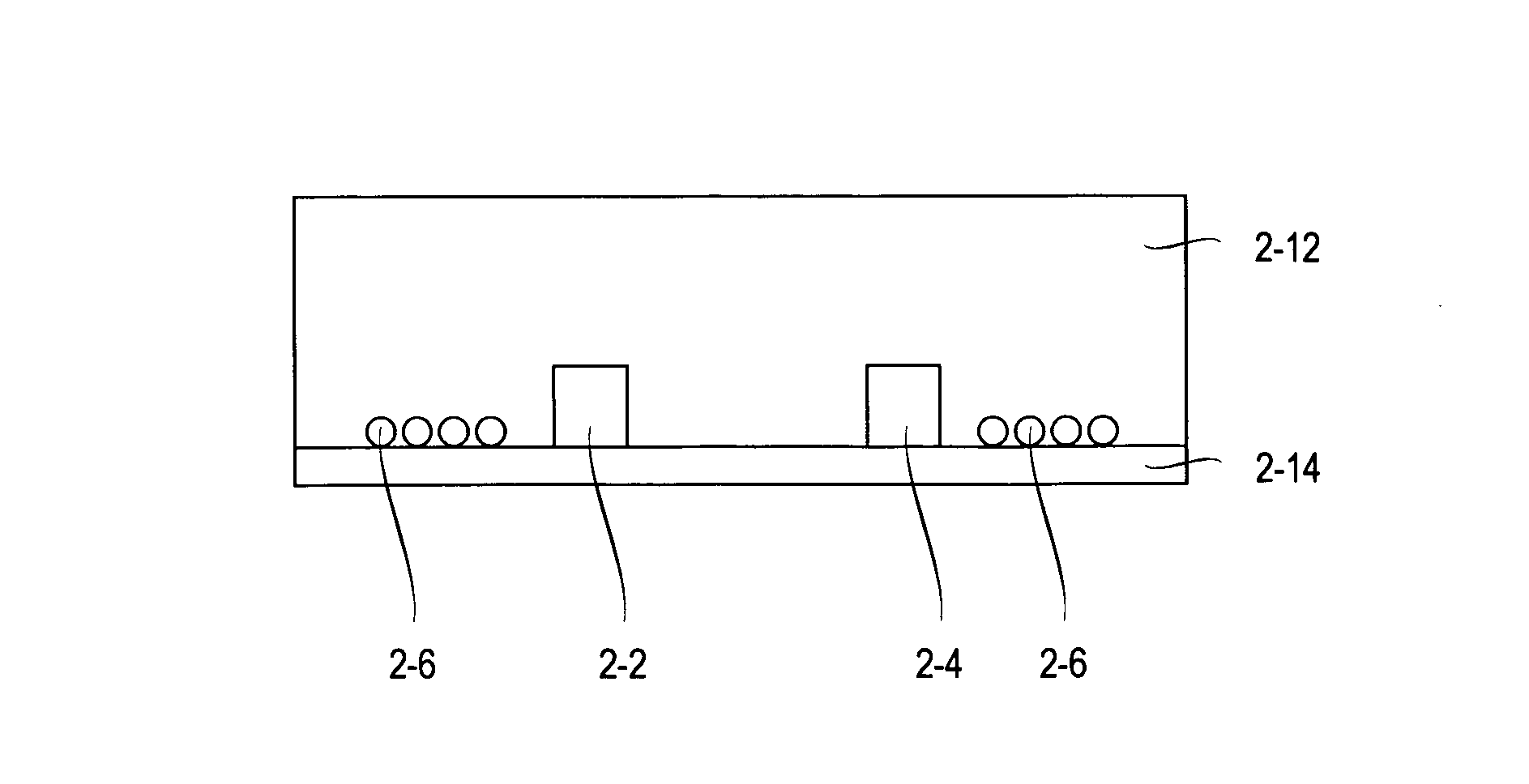
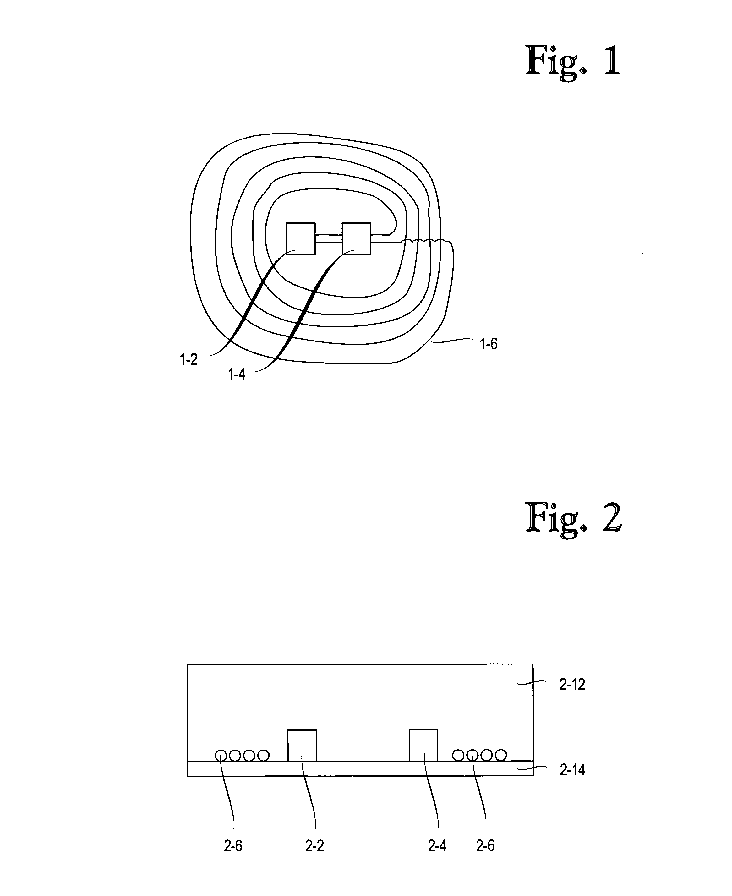
[0016]In an inductive energy transfer arrangement, energy is transferred by a magnetic field in such a way that a high-frequency first current supplied to a charging coil generates a changing magnetic field, which induces an alternating second current in a receiver coil. A receiver with the receiver coil, can be in a terminal device or in contact with the terminal device or in communication with the terminal device, and can thus be used for using the terminal device and / or for charging the terminal device or for loading the batteries of the terminal device or apparatus. The receiver coil can also be in a terminal device or in contact with the terminal device or in communication with the terminal device. The created magnetic field can be spherical, and the receiver should find this field in order to be charged or forwarding the charging energy.

[0017]The invention and its embodiments provide an indication device for efficient wireless charging. The indication device can be e.g. a char...


PUM

PropertyMeasurementUnit
thicknessaaaaaaaaaa
thicknessaaaaaaaaaa
diameteraaaaaaaaaa

Abstract

The invention relates to an indication device, comprising means for receiving magnetic energy and means for transforming said received magnetic energy into light.

Description

FIELD OF THE INVENTION[0001]The invention relates to a charging method and apparatus, and more particularly to an arrangement for a wireless charger.BACKGROUND OF THE INVENTION[0002]In a wireless charging a power surface is provided comprising one or more energy transfer units or transmitters by means of which a charging current may be supplied to a terminal device or a receiver on the surface. For the system to function efficiently, it is important that the transmitter of energy and the receiver of energy are not misplaced in relation to each other. If this happens, the charging is inefficient or even worse, no charging occurs. This is due to the fact that a magnetic field of a primary side, i.e. of the energy transmitting side does not reach magnetic receiving elements of a secondary side, i.e. of the energy receiving side. The accurate placing becomes even more challenging when an existing surface is to be changed to a wireless charging surface without changing the original purpo...

Claims


Application Information

Patent Timeline
Patent Type & Authority Applications(United States)
IPC IPC(8): H05B37/00H01F38/14H02J7/00
CPCH01F38/14H02J5/005H02J7/0042H02J7/025H05B37/00H02J17/00H02J7/00H02J7/0052H02J7/027H04B5/0037H04B5/0075H02J50/12H05B47/00H02J7/02H02J50/402H02J7/0047H02J50/80H02J50/90
Inventor NISKALA, TIMOKOSKINEN, MIKKOITKONEN, MAIJASAZONOV, PETER
Owner POWERMAT TECHNOLOGIES
Why Eureka
Try Eureka