Systems and methods for sensing an acoustic signal using microelectromechanical systems technology

a microelectromechanical and signal technology, applied in the direction of piezoelectric/electrostrictive transducers, transducer circuits, vibration measurement in solids, etc., can solve the problems of hindering certain microphone applications, hindering the current trend of microphone and acoustic system miniaturization, and deficiency of conventional approaches

Inactive Publication Date: 2005-02-22
TEXTRON SYST
View PDF13 Cites 41 Cited by
  • Summary
  • Abstract
  • Description
  • Claims
  • Application Information

AI Technical Summary

Benefits of technology

In one arrangement, the processing circuit includes a correlation stage that digitizes the wind velocity signal, correlates the digitized wind velocity signal with a series of wind pressure values from a lookup table, and provides the series of wind pressure values in the form of a correlation signal. Here, the processing circuit further includes an output stage that (i) receives the correlation signal from the correlation stage, (ii) receives the sound and wind signal from the microphone, and (iii) subtracts the series of wind pressure values from the sound and wind pressure signal to provide the output signal. This arrangement enables an algorithm to be applied to the wind velocity signal. In this arrangement, the system does not need the conversion stage, or the conversion stage can be bypassed.

Problems solved by technology

Unfortunately, there are deficiencies to conventional approaches to reducing wind noise sensed by a microphone.
For example, the above-described conventional windscreens tend to be bulky thus hindering certain microphone applications (e.g., applications in hearing aids, hands-free telephone equipment, covert surveillance equipment, etc.).
Additionally, the bulkiness of such windscreens hinders the current trend of microphone and acoustic system miniaturization (e.g., palm-sized camcorders, pocket-sized cellular telephones, etc.).
Furthermore, windscreens cannot be miniaturized if their effectiveness in wind noise removal is to be maintained.
Additionally, in connection with the above-described conventional approach to electronically removing wind noise from a sound and wind pressure signal sensed by a microphone surrounded by a set of hot-wire anemometers, the approach provided mixed results and has not been shown to remove wind noise as effectively as windscreens.
Also, as the wind passed the microphone toward the set of anemometers, the air flow around the microphone could have distorted the wind velocity at the anemometers thus introducing inaccuracies into the system.
Furthermore, the approach worked well only when the wind was substantially normal incident to the microphone diaphragm.
Moreover, there are implementation deficiencies with the above-described conventional approaches to electronically removing wind noise.
Furthermore, those approaches subtracted wind pressure data from a sound and wind signal after the signal information was digitized and stored in memory thus requiring computer memory and providing latency.
Such post-processing approaches are unsuitable for certain applications such as in acoustic systems requiring active (i.e., real-time) wind noise removal, e.g., live broadcasts, cellular phones, military / defense ground sensors, hearing aids, etc.

Method used


Image

  • Systems and methods for sensing an acoustic signal using microelectromechanical systems technology
  • Systems and methods for sensing an acoustic signal using microelectromechanical systems technology
  • Systems and methods for sensing an acoustic signal using microelectromechanical systems technology

Examples


Embodiment Construction

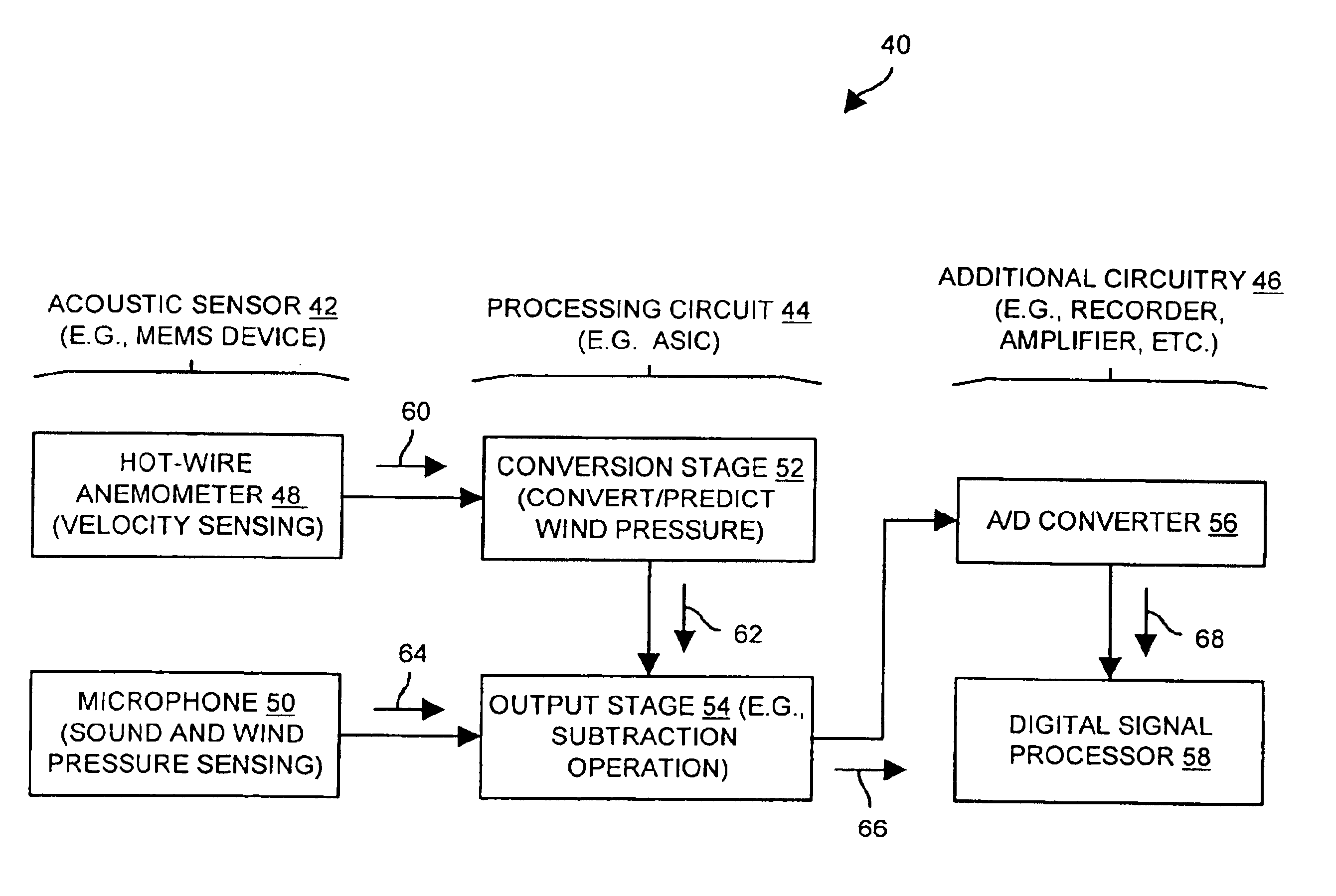
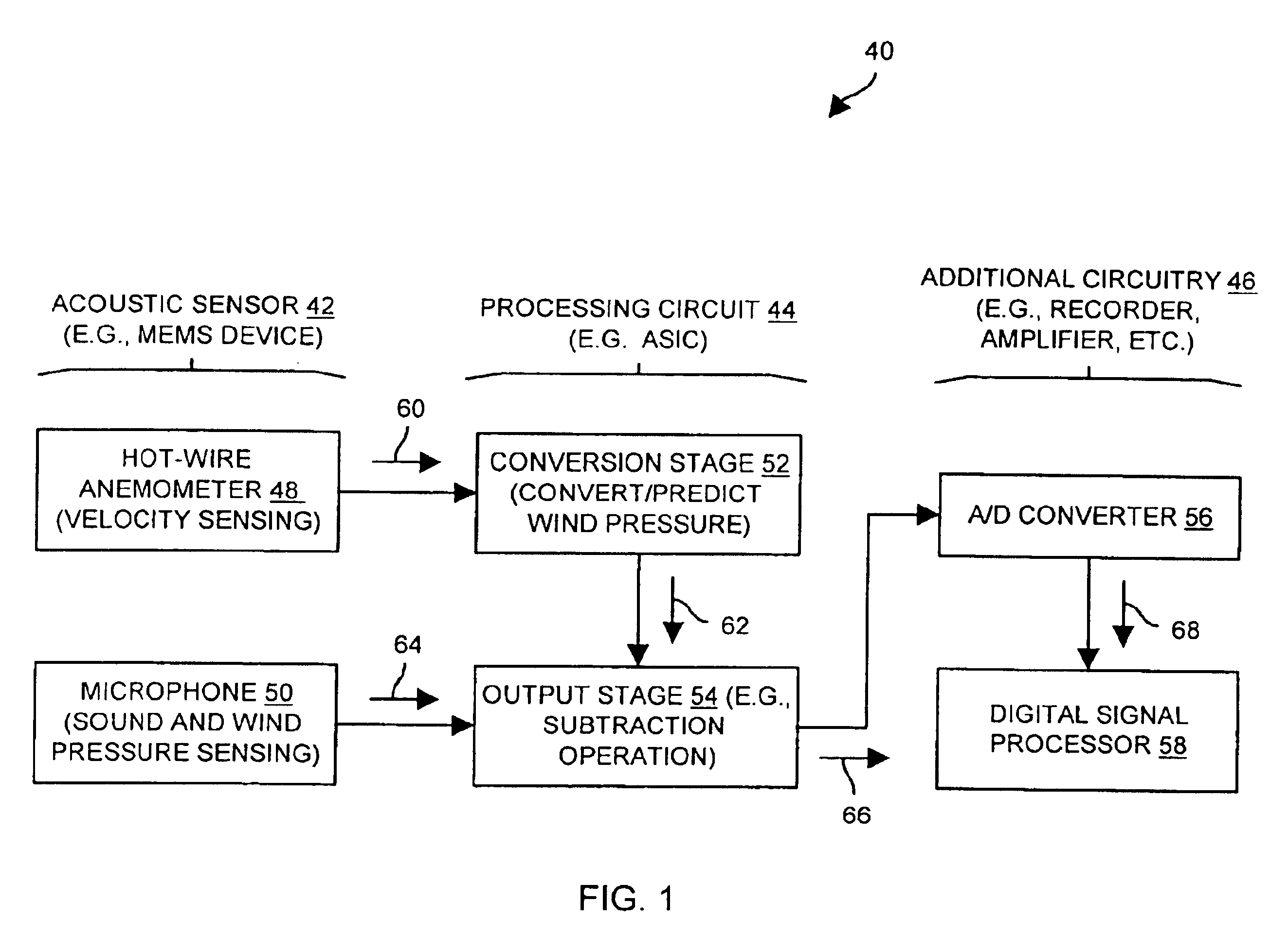
Embodiments of the invention are directed to techniques for obtaining an acoustical signal using microelectromechanical systems (MEMS) technology. For example, sensing elements such as a microphone and a hot-wire anemometer can be essentially collocated (e.g., can reside at a location with a minute finite separation) in a MEMS device. Accordingly, wind velocity as well as sound and wind pressure can be measured at essentially the same location. As a result, a wind pressure signal can be generated based on the wind velocity at that location, and then subtracted from the sound and wind pressure obtained at that location thus providing accurate sound with wind noise removed.

FIG. 1 shows an acoustic system 40 which is suitable for use by the invention. The acoustic system 40 includes an acoustic sensor 42 and a processing circuit 44. The acoustic system 40 can further include additional circuitry 46 (e.g., a recorder, an amplifier, a transmitter, etc.). The acoustic sensor 42 includes a...


PUM


Abstract

An acoustic system has an acoustic sensor and a processing circuit. The acoustic sensor includes a base, a microphone having a microphone diaphragm supported by the base, and a hot-wire anemometer having a set of hot-wire extending members supported by the base. The set of hot-wire extending members defines a plane which is substantially parallel to the microphone diaphragm. The processing circuit receives a sound and wind pressure signal from the microphone and a wind velocity signal from the hot-wire anemometer, and provides an output signal based on the sound and wind pressure signal from the microphone and the wind velocity signal from the hot-wire anemometer (e.g., accurate sound with wind noise removed). The configuration of the hot-wire extending members defining a plane which is substantially parallel to the microphone diaphragm can be easily implemented in a MEMS device making the configuration suitable for miniaturized applications.

Description

BACKGROUND OF THE INVENTIONA microphone is a transducer that converts patterns of air pressure (i.e., an acoustic signal) into an electrical signal. In a typical dynamic microphone, a microphone diaphragm moves a coil relative to a magnetic field in order to cause current to flow within the coil. In a typical condenser microphone, a microphone diaphragm (e.g., a charged metallic plate, an electret, etc.) moves relative to a rigid backplate in order to cause current to flow from a power supply attempting to maintain a constant potential difference between the microphone diaphragm and the rigid backplate.Wind noise can interfere with a microphone's ability to sense an acoustic signal. For example, when a person speaks into a microphone, wind noise can mask out the person's voice thus obscuring the person's voice from a device attached to the microphone (e.g., an amplifier, a recorder, a transmitter, a speaker, etc.). Wind noise can also mask out vital acoustic information reducing the...

Claims


Application Information

Patent Timeline
Patent Type & Authority Patents(United States)
IPC IPC(8): H04R23/00G01S7/521G01P5/12H04R3/00H04R23/02
CPCH04R23/00
Inventor CHOE, HOWARD C.BULAT, EMEL S.
Owner TEXTRON SYST
Why Eureka
Try Eureka