
Battery charging system for hybrid electric vehicles

a hybrid electric vehicle and charging system technology, applied in the direction of battery/fuel cell control arrangement, hybrid vehicle features, vehicle sub-unit features, etc., can solve the problems of over-powering of low-voltage batteries, etc., to achieve good energy efficiency

Inactive Publication Date: 2006-10-19
MITSUBISHI FUSO TRUCK AND BUS CORPORATION
View PDF1 Cites 74 Cited by
  • Summary
  • Abstract
  • Description
  • Claims
  • Application Information

AI Technical Summary

Benefits of technology

[0022] The present invention has been made in view of the circumstances described above. Accordingly, it is the primary object of the present invention to provide a battery charging system for hybrid electric vehicles which is capable of charging a low voltage battery with good energy efficiency.
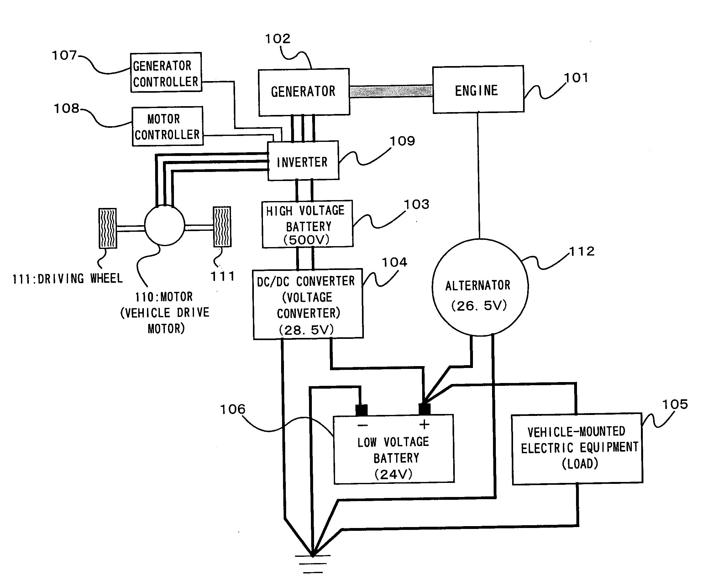
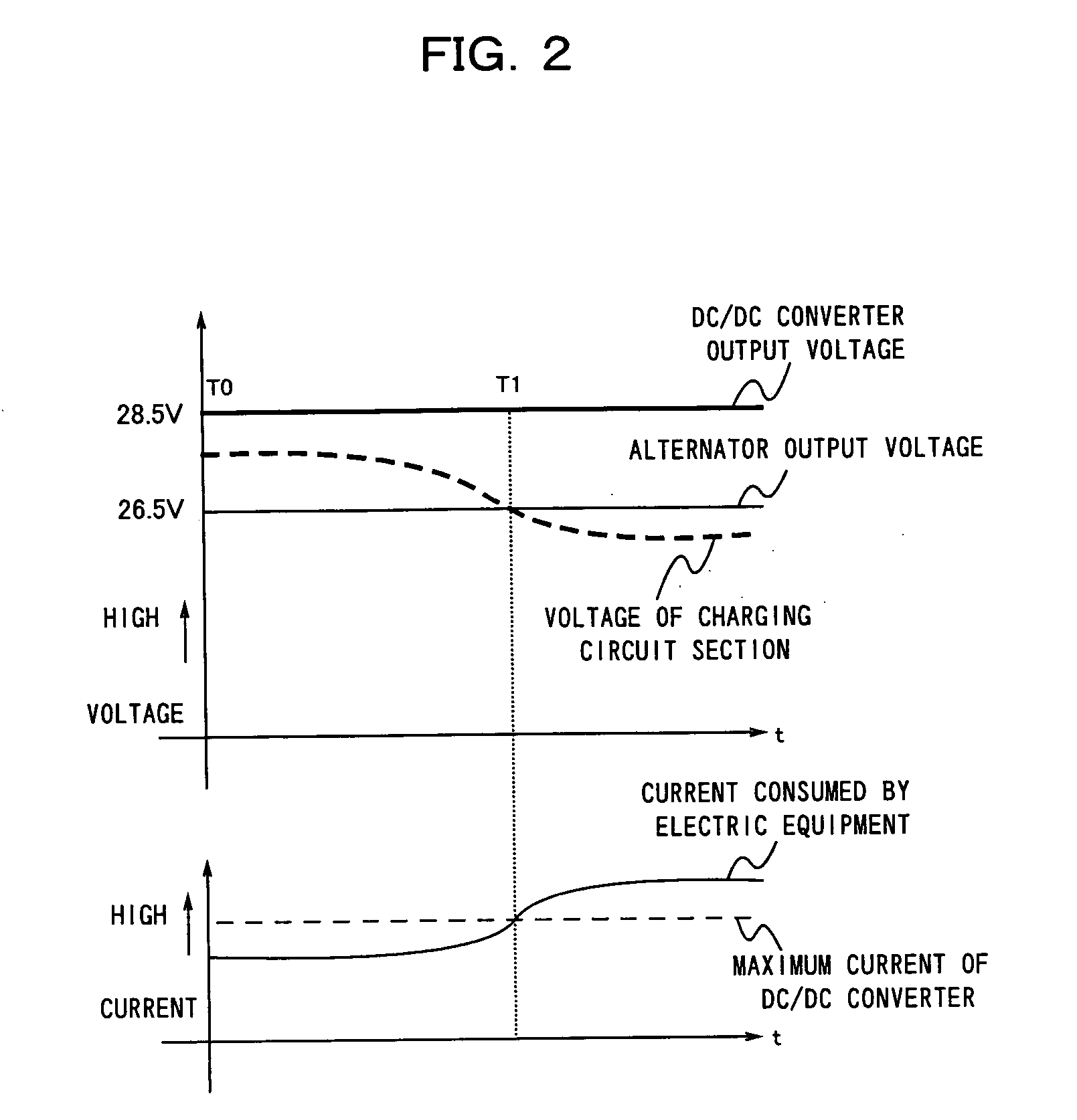
[0024] According to the battery charging system of the present invention, the output voltage of the alternator is lower than the first voltage and higher than the rated voltage of the low voltage battery. Therefore, in the case where a demand for electric power from the low voltage battery is not so large, electric power from the voltage converter is mainly stored in the low voltage battery. Thus, in charging the low voltage battery with a simpler construction, charging can be performed with good energy efficiency.
[0026] In the case where a demand for electric power from the low voltage battery is not so large, the supply of electric power from the alternator to the low voltage battery can be reliably prevented.
[0028] In this case, in charging the low voltage battery whose rated voltage is 24 V, charging can be performed with good energy efficiency.

Problems solved by technology

The power consumption of the low voltage battery 106 becomes extremely high when particular electric equipment with high power consumption (e.g. an air conditioner, headlights, etc.) is being operated.
However, when such particular electric equipment is not operated, the power consumption of the low voltage battery 106 does not become so high.
However, in the case where the power consumption of the low voltage battery 106 is not high, the voltage conversion quantity of the DC / DC converter 104 will leave too much margin and exceed specifications.
Normally, a DC / DC converter becomes larger in size and higher in cost as its voltage conversion quantity becomes greater.
The torque consumed by the alternator 112 to generate electric power results in an increase in fuel costs of the engine.

Method used


Image

  • Battery charging system for hybrid electric vehicles
  • Battery charging system for hybrid electric vehicles
  • Battery charging system for hybrid electric vehicles

Examples


Embodiment Construction

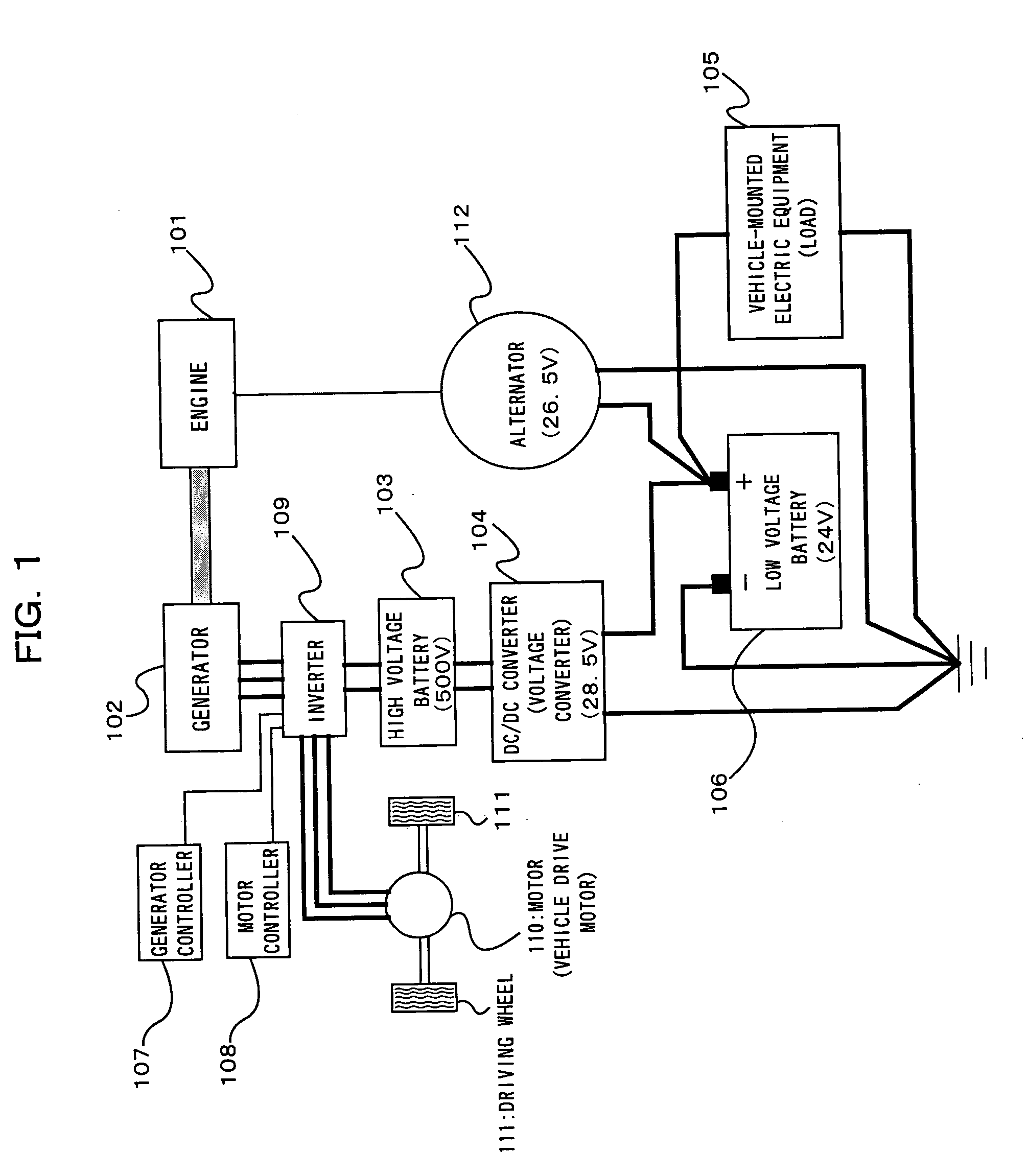
[0033] Referring to FIGS. 1 and 2, there is shown a battery charging system constructed in accordance with a preferred embodiment of the present invention. In FIG. 1, the same parts as the prior art in FIG. 3 are given the same reference numerals.

[0034] As shown in FIG. 1, the battery charging system of the preferred embodiment includes an engine 101, a motor controller 108, an inverter 109, a motor 110, driving wheels 111, a generator 102 that is driven by the engine 101, a high voltage battery 103, a DC / DC converter (voltage converter) 104, a low voltage battery 106 with an output voltage of 24 V, and an alternator 112 that is driven by the engine 101.

[0035] The vehicle drive motor 110 is connected to the driving wheels 111 so that power can be transmitted, and is further connected with the inverter 109. The generator 102 is connected to the engine 101 so that it can generate electric power by being driven with the engine 101. The generator 102 is controlled by the generator con...


PUM


Abstract

A battery charging system for hybrid electric vehicles that is capable of charging a low voltage battery with good energy efficiency. The battery charging system includes a high voltage battery for supplying electric power to a vehicle drive motor; and a voltage converter for converting a voltage, input from the high voltage battery, to a first voltage and outputting the first voltage. The battery charging system further includes a low voltage battery that is charged with the first voltage from the voltage converter; and an alternator, which is driven by an engine, connected with the low voltage battery in parallel with the voltage converter. The output voltage of the alternator is lower than the first voltage and higher than the rated voltage of the low voltage battery.

Description

BACKGROUND OF THE INVENTION [0001] (1) Field of the Invention [0002] The present invention relates to a battery charging system that is suitable for use in hybrid electric vehicles. [0003] (2) Description of the Related Art [0004] Hybrid electric vehicles have been put to practical use in recent years and include a generator for generating electric power by being driven with an engine, a vehicle drive battery (high voltage battery), a vehicle drive motor, etc. Hybrid electric vehicles are roughly classified into three types: (1) a parallel type in which driving wheels are rotated by using the driving force of the engine and the driving force of the vehicle drive motor in combination; (2) a series type in which driving wheels are rotated by the vehicle drive motor driven with electric power generated by driving the engine; and (3) a combination type of them. [0005] In addition to the vehicle drive battery with a relatively high voltage (e.g. about 500 V), hybrid electric vehicles are...

Claims


Application Information

Patent Timeline
IPC IPC(8): H02J7/00B60L8/00B60K6/40B60K6/46B60L50/15B60W10/26B60W20/00
CPCB60K6/28B60K6/46B60L11/1868B60L2210/10B60W10/26B60Y2400/112Y02T10/6217Y02T10/6278Y02T10/7005Y02T10/7066Y02T10/7216B60W20/00B60L58/20Y02T10/62Y02T10/70Y02T10/72Y02T10/7072B60L50/50B60W20/13
Inventor HORII, YUSUKE
Owner MITSUBISHI FUSO TRUCK AND BUS CORPORATION
Learn More