Internal capacitor linear regulator with transient dip compensator for internal-switch switching regulator

Active Publication Date: 2013-03-28
AVAGO TECH INT SALES PTE LTD
View PDF4 Cites 17 Cited by
  • Summary
  • Abstract
  • Description
  • Claims
  • Application Information

AI Technical Summary

Problems solved by technology

Such arrangements are inconvenient in part because an integrated circuit chip includ

Method used


Image

  • Internal capacitor linear regulator with transient dip compensator for internal-switch switching regulator
  • Internal capacitor linear regulator with transient dip compensator for internal-switch switching regulator
  • Internal capacitor linear regulator with transient dip compensator for internal-switch switching regulator

Examples


Embodiment Construction

[0018]It is to be appreciated that the Detailed Description section, and not the Summary and Abstract sections, is intended to be used to interpret the claims. The Summary and Abstract sections may set forth one or more but not all exemplary embodiments of the present invention as contemplated by the inventor(s), and thus, are not intended to limit the present invention and the appended claims in any way.

[0019]Furthermore, it should be understood that spatial descriptions (e.g., “above”, “below”, “left,”“right,”“up”, “down”, “top”, “bottom”, etc.) used herein are for purposes of illustration only, and that practical implementations of the structures described herein can be spatially arranged in any orientation or manner.

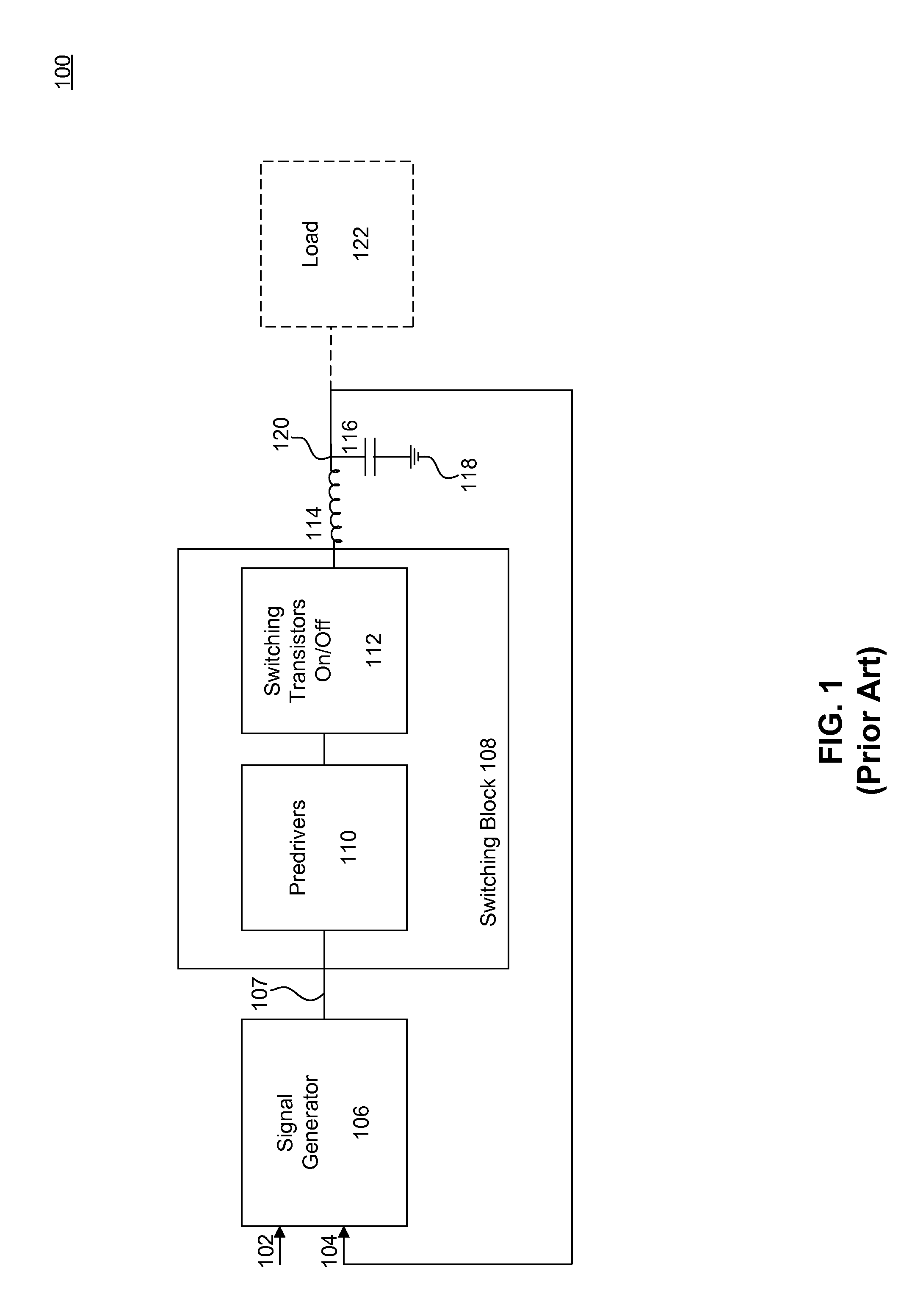
[0020]FIG. 1 (Prior Art) is a block diagram of a known switching regulator 100. The switching regulator 100 includes a signal generator 106 which is provided an unregulated voltage 102 and a loopback voltage 104. The signal generator 106 provides a signal 107 to a sw...


PUM


Abstract

A switching regulator arrangement utilizes internal capacitors rather than external capacitors for driving output power transistors. Low-dropout linear voltage regulators together with a dip compensation circuit provide an intermediate supply voltage for driving power transistors under circumstances in which a supply voltage is greater than a gate drive voltage of the power transistor, allowing for a more efficient absorption of transient current.

Description

BACKGROUND[0001]1. Field of Invention[0002]Embodiments described herein generally relate to switching regulators, and more particularly integrated circuit switching regulators which generate internal supply voltages for driving the power switches. More specifically, the invention relates to switching regulators in which low-dropout voltage regulators (“LDOs”) provide an intermediate supply voltage for driving power transistors under circumstances in which a supply voltage is greater than a gate drive voltage of a power transistor of the regulator.[0003]2. Background Art[0004]Various switching regulator arrangements are intended to be operated with an external capacitor to provide low impedance for driving the power switches. Such arrangements are inconvenient in part because an integrated circuit chip including the regulator requires additional pins for connection to the external capacitor. Furthermore, there must be sufficient room in a device including the switching regulator to h...

Claims


Application Information

Patent Timeline
IPC IPC(8): G05F1/46
CPCH02M3/1588H03K2217/0081Y02B70/1466Y02B70/10
Inventor CHAN, HUA BENGCHEN, DEYULE, QUEENIE
Owner AVAGO TECH INT SALES PTE LTD
Why Eureka
Try Eureka