
LED fluorescent tube structure

Inactive Publication Date: 2013-03-28
UNITY OPTO TECH CO LTD
View PDF26 Cites 46 Cited by
  • Summary
  • Abstract
  • Description
  • Claims
  • Application Information

AI Technical Summary

Benefits of technology

The present invention provides an LED fluorescent tube structure that solves the problem of a loose assembled structure and ensures a sufficient spatial distance between the heat dissipating opening of the transparent cover. It also increases the overall strength of the assembled structure to prevent bending or deformation. The cooling block is thickened to improve stability. A reinforcing plate is installed on the partition to support the pair of first hooks and enhance the stability of the assembled structure. Bumps are included in the side covers to seal the heat dissipating opening tightly to prevent bugs from entering.

Problems solved by technology

Since it is necessary to secure the screws one by one in an assembling process, the manufacture takes much time and manpower and uses a large quantity of screws that incur a higher manufacturing cost.
Furthermore, the securing force cannot be controlled easily or evenly.
As a result, the LED lamp panel may be warped or deformed.
In general, an LED fluorescent tube usually has a lamp base which is not installed tightly, and there is a potential risk of touching the lamp base and getting an electric shock by accident when a user changes the fluorescent tube.
However, if a long lamp tube is used, the thickness of the side arms is insufficient to provide the required strength and the included angle between the side arms and the heat dissipating device is smaller than 90 degrees.
Thus it is difficult to support the heat dissipating device effectively, and both end portions and the central portion of the heat dissipating device may be deformed or bent easily to cause a partially closed heat dissipating opening or affect the aesthetic look and the heat dissipating effect adversely, and such lamp structure definitely requires improvements.

Method used


Image

  • LED fluorescent tube structure
  • LED fluorescent tube structure
  • LED fluorescent tube structure

Examples


Embodiment Construction

[0022]The technical content of the present invention will become apparent by the detailed description of the following embodiments and the illustration of related drawings as follows.

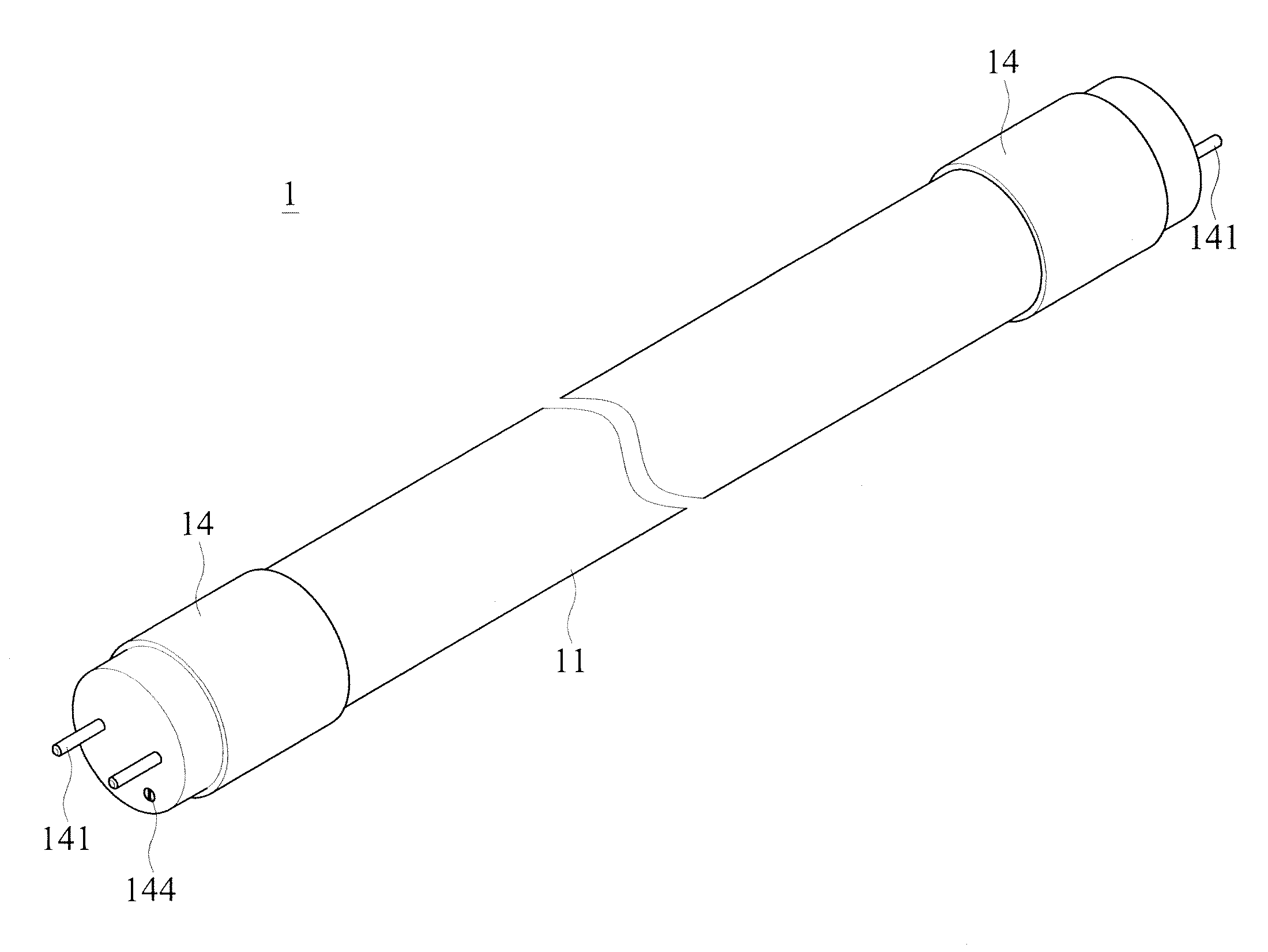
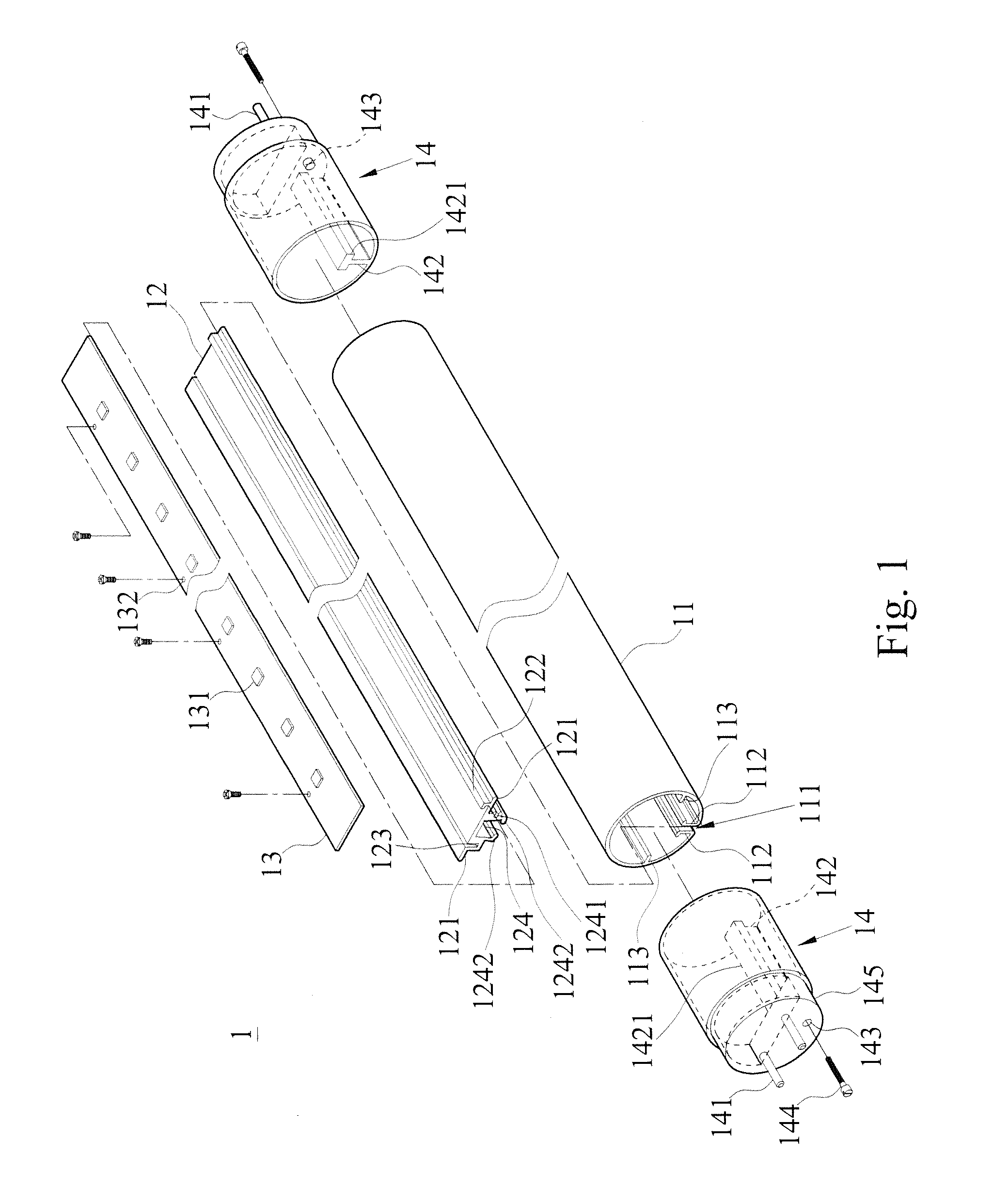
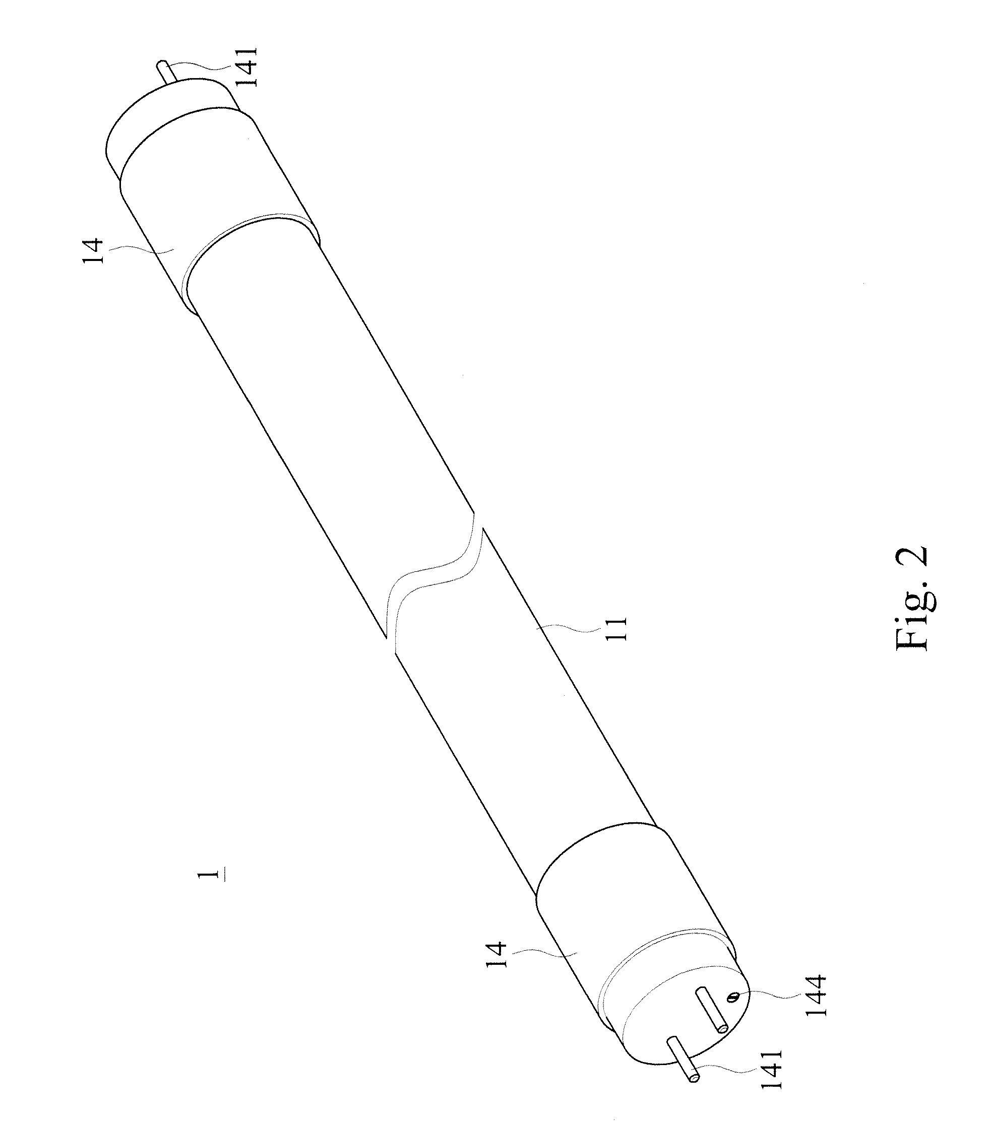
[0023]With reference to FIGS. 1 to 4 for an exploded view, a perspective view and cross-sectional views of an LED fluorescent tube structure in accordance with a preferred embodiment of the present invention respectively, the LED fluorescent tube structure 1 comprises a transparent cover 11, a cooling block 12, an LED lamp panel 13 and a pair of side covers 14.

[0024]Wherein, the transparent cover 11 is a circular tabular structure made of an elastic transparent material (such as a plastic material) which is an electrically insulator capable of avoiding electric shocks, and a heat dissipating opening 111 is formed axially along the transparent cover 11, and the heat dissipating opening 111 includes a pair of first hooks 112 inwardly extended towards the transparent cover 11. Since the transparent cover 1...


PUM


Abstract

An LED fluorescent tube structure includes a transparent cover, a cooling block, at least one LED lamp panel and a pair of side covers. The transparent cover includes a heat dissipating opening having a pair of first hooks, and an embedding slot. The top of the cooling block is provided for carrying the LED lamp panel and embedded into the transparent cover. A latch groove at the bottom of the cooling block has a tapered opening for latching the transparent cover. The side covers are sealed onto both end portions of the transparent cover respectively. The latch groove is designed with an angle for enhancing a latching effect to assure the spatial distance of the heat dissipating opening. The latch groove at a position connecting the cooling block is thickened to enhance the strength of the cooling block, prevent deformations, and improve the aesthetic look and using effect.

Description

BACKGROUND OF THE INVENTION[0001]1. Field of the Invention[0002]The present invention relates to the field of illumination devices, in particular to an LED fluorescent tube structure that complies with the illumination safety regulations of different countries and provides a good heat dissipation effect.[0003]2. Description of the Related Art[0004]With the advantages of power saving, high brightness, long service life and mercury pollution-free feature, light emitting diodes (LED) are applied extensively for manufacturing illumination lamps including LED fluorescent tubes and LED bulbs. The LED fluorescent tube and LED bulbs have gradually replaced traditional fluorescent lamps and bulbs and meet the power saving and carbon reduction requirements.[0005]For example, the LED fluorescent tube generally comprises a lamp cover, a lamp base and at least one LED lamp panel, wherein the LED lamp panel includes a plurality of LEDs installed thereon; the LED lamp panel is mounted onto the lam...

Claims


Application Information

Patent Timeline
IPC IPC(8): F21V29/00
CPCF21K9/17F21V17/104F21V17/12F21V29/89F21Y2101/02F21Y2103/003F21V19/0055F21K9/27F21Y2103/10F21Y2115/10
Inventor WU, CHIH-HSIENHSIAO, PO-WEN
Owner UNITY OPTO TECH CO LTD
Learn More