Light for an Aircraft

a technology for aircraft and light, applied in the field of light for aircraft, can solve the problem that the projection apparatus cannot be used in the lamp

Inactive Publication Date: 2013-03-28
GOODRICH LIGHTING SYST
View PDF1 Cites 17 Cited by
  • Summary
  • Abstract
  • Description
  • Claims
  • Application Information

AI Technical Summary

Benefits of technology

[0043]The set-up according to the present invention allows for the addition of a fourth group of fourth LEDs not included within the first reflector of the first optical unit. The fourth group of fourth LEDs can be located within the second optical unit or outside both optical units. The fourth LEDs contribute to a desired light intensity contribution (if necessary). The fourth LEDs should be located such that they do not block light exiting the second optical unit but add to that light. The fourth group of fourth LEDs can be used in combination with additional optical elements like TIR-based optical elements (Total Internal Reflection optical elements).

Problems solved by technology

Such a projection apparatus cannot be used in a lamp in which the light has to be directed in a pre-determined special light intensity distribution as in case of an aircraft light.

Method used


Image

  • Light for an Aircraft
  • Light for an Aircraft
  • Light for an Aircraft

Examples


Embodiment Construction

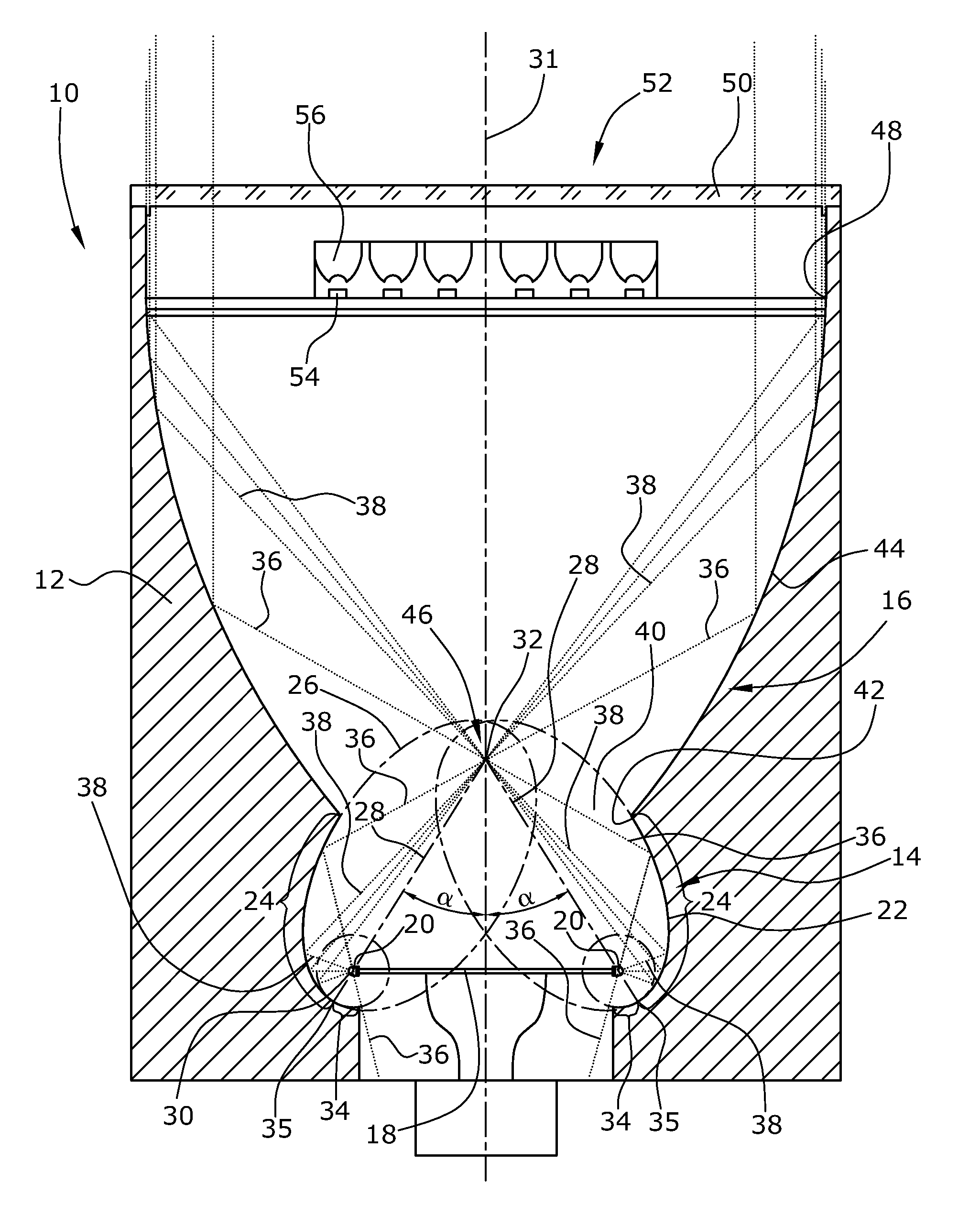
[0055]In FIG. 1 of an aircraft light 10 is shown which is designed as a take-off light and in which the present invention can be used. The light 10 comprises a housing 12 defining a hollow space provided with a first and a second optical system 14,16.

[0056]The first optical system 14 is of the reflection type and comprises a holder 18 designed e.g. as a circular disk or ring with a plurality of first LEDs 20 arranged at the circumference of the disk or ring 18. The first LEDs 20 can be of the same type and the same color or can be different in type and color. The holder 18 is arranged within a first reflector 22 defined by two types of reflective partial surfaces formed at the inner surface of the hollow housing 12.

[0057]A first reflective surface of the first reflector 22 is elliptically shaped. This elliptical reflective partial surface 24 is spanned by a part of the circumference of an ellipse 26 which is inclined. Said ellipse 26 comprises an axis 28 or chord on which a first fo...


PUM


Abstract

A light for an aircraft comprises a holder for carrying a first group of light emitting diodes arranged along a curvilinear line and a first reflector having an elliptic reflective partial surface defining a plurality of focal points forming a first curvilinear focal line coinciding with the light emitting sites of the first group of light emitting diodes and second focal point or curvilinear focal line. The light further includes a second optical unit comprising a single further focal point or curvilinear focal line that coincides with the second focal point or focal line of the first reflector. The light further includes a second group of light emitting diodes displaced axially with respect to the first light emitting diodes, which emit light that bypasses the second focal point or focal line of the first reflector of the first optical unit.

Description

BACKGROUND OF THE INVENTION[0001]1. Field of the Invention[0002]The present invention relates to a light for an aircraft and, in particular, to an external light for an aircraft. While the present invention can be used primarily for each type of aircraft light, preferably the present invention is for a head light; taxi light, and runway turn-off light of an aircraft.[0003]2. Description of the Prior Art[0004]In the past, in the technical field of aerospace applications, light sources have been based on gas discharge technology or filaments. For several years, aircraft lights based on LED technology have found ever stronger commercial use. Examples for LED-based aircraft lights for different purposes are disclosed in U.S. Pat. No. 6,679,618, U.S. Pat. No. 7,572,030, US-A-2007 / 0164875, WO-A-2009 / 156349, EP-B-1 217 663, EP-B-1 264 767, EP-B-1 552 983, EP-B-1 836 437, and GB-B-2,350,176.[0005]In order to fulfill the official requirements of the Federal Aviation Association (FAA) with re...

Claims


Application Information

Patent Timeline
Patent Type & Authority Applications(United States)
IPC IPC(8): B64D47/06F21W107/30H05B44/00
CPCB64D47/06B64D47/04F21V5/046F21V7/0016F21V7/0033F21V7/08F21V7/0058F21V13/04B64D2203/00F21Y2101/02F21Y2103/022F21Y2113/02F21V13/02F21Y2103/33F21Y2113/20F21Y2115/10
Inventor HESSLING, ANDREGRIESBACH, MARTIN
Owner GOODRICH LIGHTING SYST
Why Eureka
Try Eureka