Network system and network redundancy method

a network system and network redundancy technology, applied in the field of network systems, can solve the problems of limiting availability and expandability, and the switch fails to receive control information,

Active Publication Date: 2013-03-28
NEC CORP
View PDF2 Cites 26 Cited by
  • Summary
  • Abstract
  • Description
  • Claims
  • Application Information

AI Technical Summary

Benefits of technology

[0031]In a network system in which a switch for forwarding packets and a control server which determines route information are separated, the redundancy by the in-band control channel is achieved.

Problems solved by technology

In this case, in order to prevent the communication between the switch and the control server from delaying and being interrupted, it is desired that the control channel is a dedicated line; however, a dedicated port for the switch and a dedicated link for the network are required to use the control channel as the dedicated line, and thus availability and expandability are restricted.
In addition, in the case where the dedicated line of the control channel is disconnected, the switch fails to receive the control information.

Method used


Image

  • Network system and network redundancy method
  • Network system and network redundancy method
  • Network system and network redundancy method

Examples


first embodiment

[0052]Referring to attached drawings, a first embodiment of the present invention will be explained below.

[Basic Configuration]

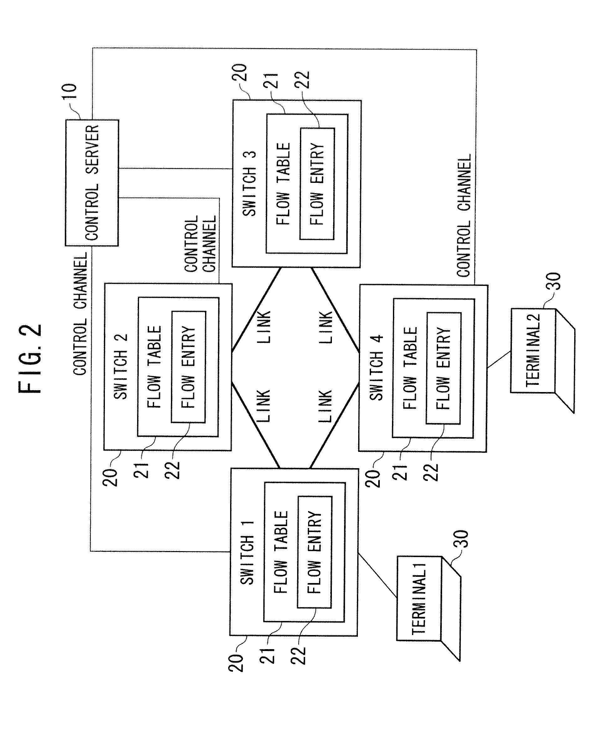
[0053]As shown in FIG. 6A and FIG. 6B, a network system of the present invention includes an out-of-band control server 100, a switch 200, and an in-band control server 300.

[0054]The out-of-band control server 100 has a switch information management unit 110, a redundancy control server management unit 120, a control channel connection unit 130, a control message processing unit 140, and route information 150.

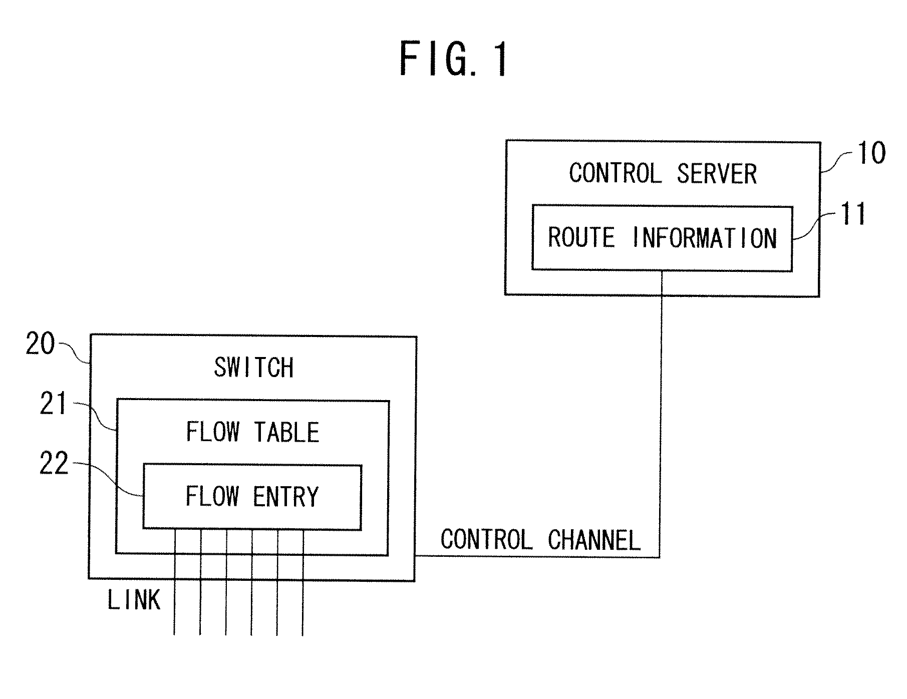
[0055]The switch 200 has a control server information management unit 210, a control channel connection unit 230, a control message processing unit 240, and a flow table 260.

[0056]The in-band control server 300 has a switch information management unit 310, a redundancy control server management unit 320, a control channel connection unit 330, a control message processing unit 340, and route information 350.

[0057]The out-of-band control server 100, the s...

second embodiment

[0150]A second embodiment of the present invention will be explained below.

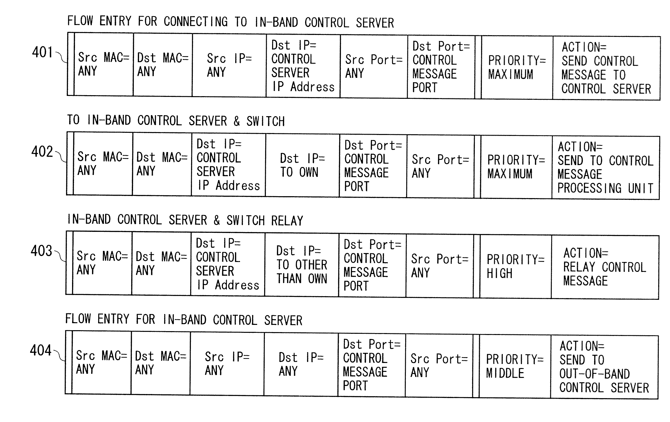
[0151]In the case where a destination port number or a source port of TCP is defined in a protocol of a control message process (for example, TCP port number is 9999), the switch 200 can extract a control message from a flowing data traffic by using a flow entry for control message detection.

[0152]The control message is sent to own out-of-band control server, the out-of-band control server can extract a source IP address of other control servers from a header of the control message, and a connection to other control server can be tried.

[Features of the Present Invention]

[0153]The present invention realizes redundancy of the control channel due to the out-of-band control server and to the in-band control server, in the switch for forwarding a packet and the control server for determining a route.

[0154]The present invention has a mechanism for registering a flow entry for control message, from the out-of-band c...


PUM


Abstract

In a network system in which a switch forwarding packets and a control server determining route information are separated, it is desired to achieve a redundancy of the control channel by an out-of-band control channel and an in-band control channel, when the switch receives a control message regarding the flow entry registration and the like based on the route information from the control server. Specifically, the separated switch and control server are connected by a control channel for sending and receiving the control message. The switch is not only connected to a control server via an out-of-band control channel by a route dedicated to the control message, but also connected to another control server via an in-band control channel by a route which is common with a normal data communication for determining the route information, to achieve a redundancy of the control channel.

Description

TECHNICAL FIELD[0001]The present invention relates to a network system, and especially relates to a network system where a switch for forwarding a packet and a control server for determining route information are separated from each other.BACKGROUND ART[0002]In recent years, as one of route control systems in a network system, a route control method that uses the OpenFlow technique, a control protocol for communication devices, has been studied.[0003]In the network system where a route control based on the open flow technique is performed, a control server such as an OFC (OpenFlow Controller) determines the route information, operates a flow table of the switch such as an OFS (OpenFlow Switch) in accordance with the determined route information, and thereby controls the behavior of the switch.[0004]The flow table is a table for registering a flow entry that defines a predetermined process (an action) to be executed to a packet conformed to a predetermined matching condition (a rule)...

Claims


Application Information

Patent Timeline
Patent Type & Authority Applications(United States)
IPC IPC(8): H04L12/56H04L45/28H04L45/586H04L45/24
CPCH04L45/22H04L45/38H04L41/0668H04L49/25H04L45/66H04L45/247H04L12/28
Inventor PHILAVONG, MINAXAYTAKASHIMA, MASANORIHIDAKA, YOUICHIIZAWA, TETSU
Owner NEC CORP
Why Eureka
Try Eureka