Electric storage apparatus

Active Publication Date: 2013-03-28
GS YUASA INT LTD
View PDF5 Cites 13 Cited by
  • Summary
  • Abstract
  • Description
  • Claims
  • Application Information

AI Technical Summary

Benefits of technology

[0010]Accordingly, it is an object of the present invention to provide an electric storage

Problems solved by technology

Therefore, the column portions impair smooth circulation of gas in the second direction.
That is, the presence of the column portions necessarily increases the pressure loss of the gas circulating in the second direction in the air vent portions.
Thus, in the cell module having

Method used


Image

  • Electric storage apparatus
  • Electric storage apparatus
  • Electric storage apparatus

Examples


Example

[0029]Hereafter, a cell module relating to an embodiment of the present invention will be described with reference to the appended drawings.

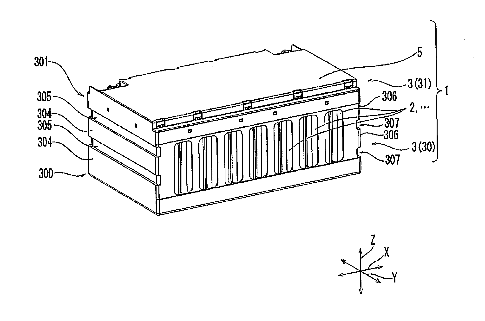
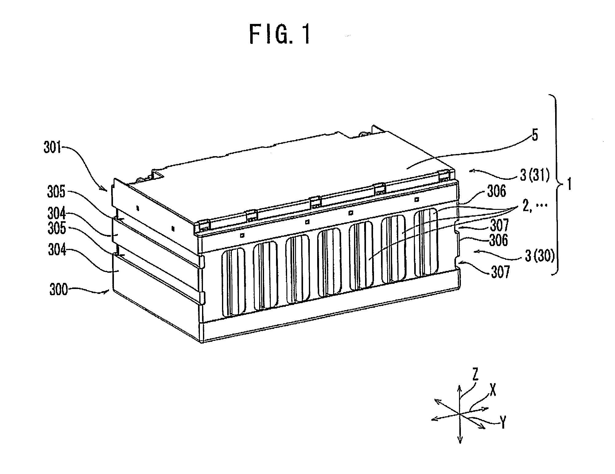
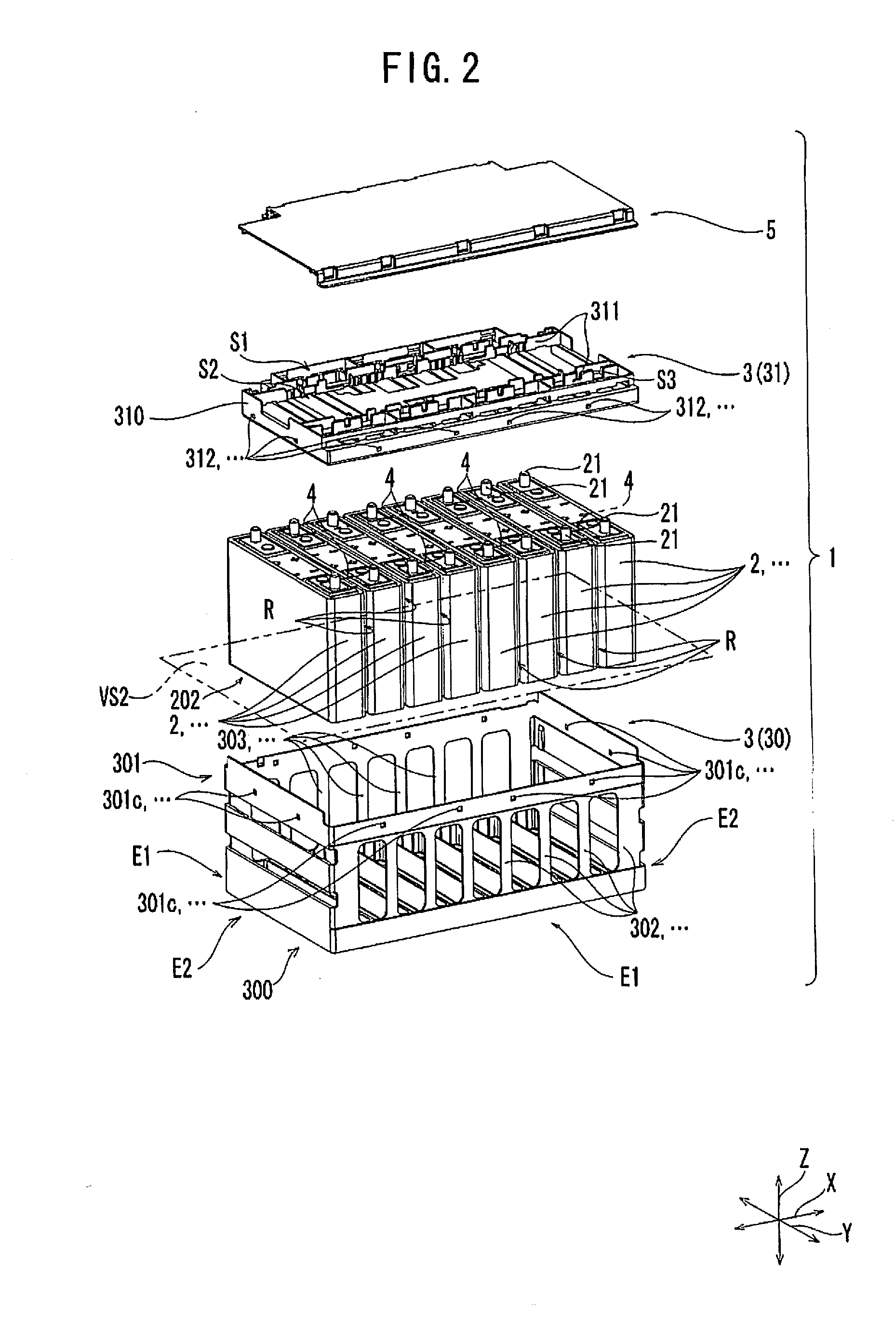
[0030]As shown in FIGS. 1 and 2, a cell module 1 includes a plurality of single cells 2, . . . , and a holder 3 that holds the plurality of single cells 2, . . . . The cell module 1 further includes a bus bar 4 that electrically interconnects single cells 2, . . . , and a cover 5 that covers the holder 3 holding the plurality of single cells 2, . . . .

[0031]Each of the plurality of single cells 2, . . . can adopt a prismatic cell having a cuboid shape in appearance, a circular cell having a circular column shape in appearance, and the like. In the present embodiment, a prismatic cell is adopted for the single cell 2.

[0032]The single cell 2 includes, as shown in FIGS. 3A and 3B, a case 20, an electrode assembly (not shown) accommodated in the case 20, and one pair of external terminals 21, 21 disposed on the outer surface of the case 20, the exte...


PUM


Abstract

An electric storage apparatus includes a holder for holding a plurality of electric storage devices. An inter-electric storage device air passage is formed between the electric storage devices. A holder body of the holder includes: at least one wall portion extending in a second direction, the at least one wall portion being opposed from outside to an electric storage device located at one end in a first direction among the plurality of electric storage devices; and an air vent portion formed side by side with the wall portion in a third direction orthogonal to the first and second directions, the air vent portion being opened to the first and second directions.

Description

CROSS REFERENCE TO RELATED APPLICATIONS[0001]The present application claims the priorities of Japanese Patent Application No. 2011-211501 and Japanese Patent Application No. 2012-194035 which is a domestic priority claiming application based on the same application, both of which are herein incorporated by reference.FIELD OF THE INVENTION[0002]The present invention relates to an electric storage apparatus including an electric storage device such as an electric cell (single cell) and a capacitor, and a holder for holding the electric storage device.BACKGROUND ART[0003]Conventionally, a cell module, which is one form of electric storage apparatus, is provided as the power source for equipment. The cell module includes a plurality of single cells which are electrically connected with each other, and a holder for holding the plurality of single cells.[0004]The plurality of single cells are aligned in a first direction. Adjacent single cells are disposed with a predetermined space there...

Claims


Application Information

Patent Timeline
IPC IPC(8): H01M2/10H01M2/12H01G9/08H01G2/04H01G2/08H01G9/26H01M10/60H01M10/613H01M10/617H01M10/6556H01M10/6557H01M10/6561H01M50/209
CPCH01M2/1077H01M10/5004H01M2220/20H01M10/5032H01M10/5067H01M10/5016H01M10/625H01M10/6563H01M10/647H01M10/613Y02E60/10H01M50/209H01M10/6566H01M50/20
Inventor NEMOTO, SEIJIWATANABE, MINORUMASUDA, YOSHIHIRO
Owner GS YUASA INT LTD
Why Eureka
Try Eureka