Automatic injection device

a technology of automatic injection and injection tube, which is applied in the direction of intravenous device, pump control, other medical devices, etc., can solve the problems of patients who are averse to self-injection, and achieve the effect of preventing the obstruction of the window

Active Publication Date: 2013-03-28
OWEN MUMFORD +1
View PDF6 Cites 72 Cited by
  • Summary
  • Abstract
  • Description
  • Claims
  • Application Information

AI Technical Summary

Benefits of technology

[0013]Furthermore and as embodied here, the automatic injection device can include a cap having an outer portion, and the first end of the housing can be configured to receive the outer portion of the cap. The outer portion of the cap can include a cap notch to align with a portion of the elongated window when the cap is received by the housing to prevent obstruction of the window. The cap can also include an inner portion. The inner portion can include a split hub projecting beyond the outer portion, and the split hub can define a hub opening. The hub opening can be aligned with at least a portion of the elongated window when the cap is received by the housing to prevent obstruction of the window. The inner portion of the cap can also include a circumferential ridge. The automatic injection device can include a needle projecting from the first end of the syringe and a needle shield surrounding at least a portion of the needle. The circumferential ridge can be configured to capture the needle shield within the inner portion of the cap when the cap is received by the housing. The needle shield can be retained in the inner portion of the cap when the cap is removed from the housing.

Problems solved by technology

Some patients, however, can be averse to carrying out self-injection, particularly if the patient has a fear of needles or limited dexterity.

Method used


Image

  • Automatic injection device
  • Automatic injection device
  • Automatic injection device

Examples


Embodiment Construction

[0068]Reference will now be made in detail to the various exemplary embodiments of the disclosed subject matter, exemplary embodiments of which are illustrated in the accompanying drawings. The structure and corresponding method of operation of the disclosed subject matter will be described in conjunction with the detailed description of the system.

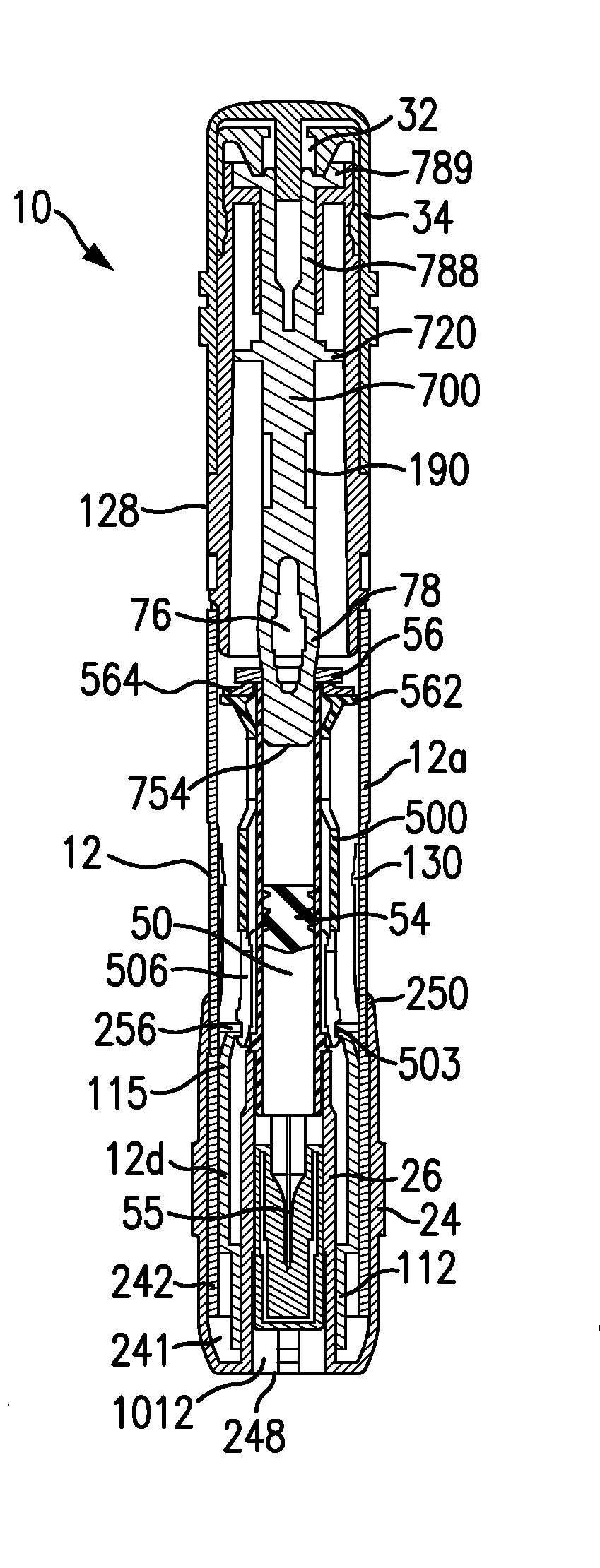
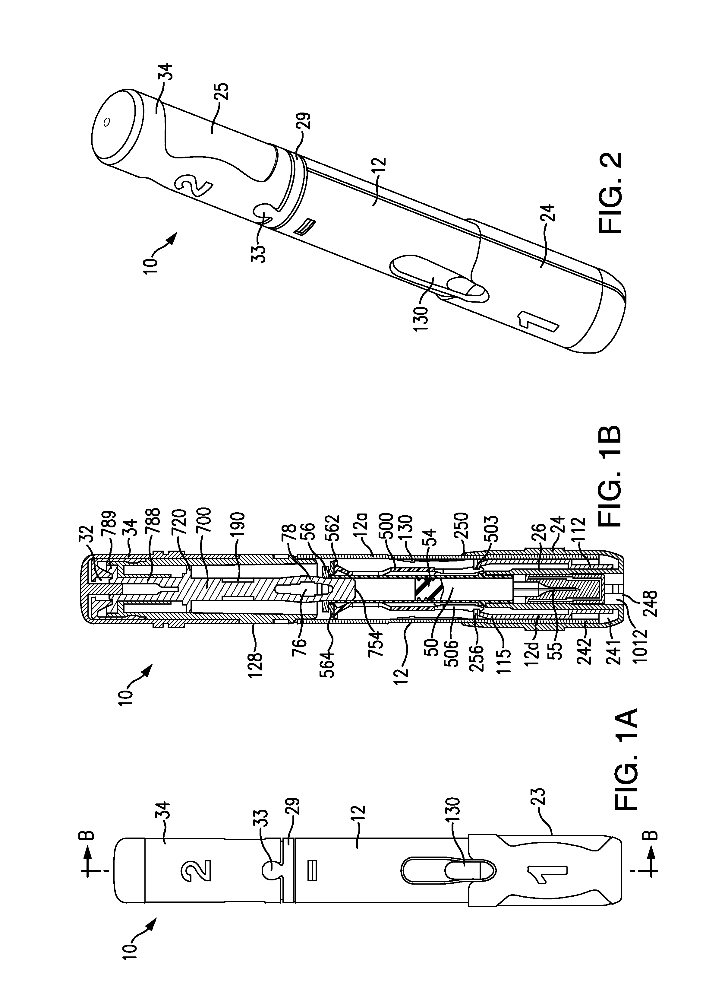
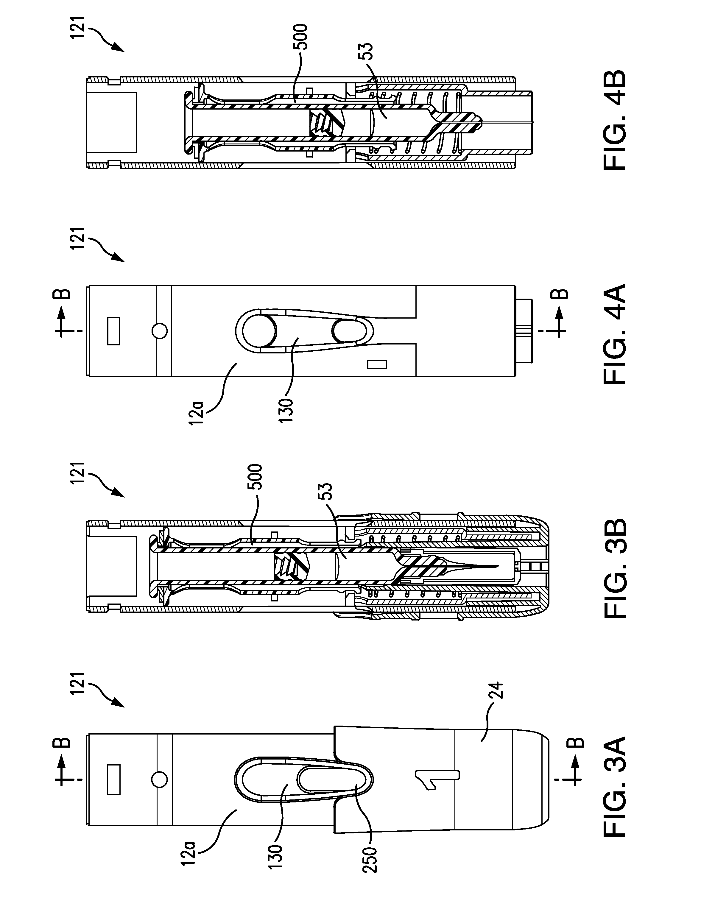
[0069]The apparatus and methods presented herein can be used for injecting any of a variety of suitable therapeutic agents or substances, such as a drug, into a patient. In one embodiment, the automatic injection device can be configured in the form of a pen, i.e., an autoinjector pen or autoinjection pen (used interchangeably herein). As used herein, an “automatic injection device” or “autoinjector” (used interchangeably herein) is intended to refer generally to a device that enables an individual (also referred to herein as a user or a patient) to self-administer a dosage of a liquid substance, such as a therapeutic agent, including a f...


PUM


Abstract

Automatic injection device includes a housing, a syringe, a plunger, and a syringe carrier. The housing includes a barrel. The barrel includes an elongated window to allow viewing of contents inside the housing. The syringe is disposed within the housing and has a reservoir. The plunger is at least partially disposed within the syringe and includes a visual indicator. The syringe carrier is disposed within the housing and configured to contain the syringe and displace the syringe within the housing between a first position and a second position. The syringe carrier has a first opening and a second opening. The first opening is configured to align with the window and the reservoir when the syringe carrier is in the first position, and the second opening is configured to align with the window and the visual indicator when the syringe carrier is in the second position.

Description

CROSS-REFERENCE TO RELATED APPLICATIONS[0001]This application claims priority to U.S. Provisional Application No. 61 / 538,098, filed on Sep. 22, 2011, which is incorporated by reference herein in its entirety.BACKGROUND[0002]1. Field of the Disclosed Subject Matter[0003]The present disclosed subject matter relates to an automatic injection device for injecting a substance, such as a therapeutic agent, into a patient.[0004]2. Description of Related Art[0005]One of the most common routes of administration for therapeutic agents, such as medications, is by injection, such as intravenous, subcutaneous or intramuscular injection. A syringe containing the medication is used for the injection, which typically is carried out by trained medical personnel. In certain instances, a patient is trained in the use of the syringe to allow for self-injection. Moreover, certain medications are formulated in pre-filled syringes for patient use, to avoid the need for the patient to fill the syringe. Som...

Claims


Application Information

Patent Timeline
Patent Type & Authority Applications(United States)
IPC IPC(8): A61M5/20
CPCA61M5/20A61M5/2033A61M2205/60A61M2205/583A61M2205/584A61M2005/2006F04C2270/041A61M5/31501A61M2005/3126
Inventor SHANG, SHERWIN S.JULIAN, JOSEPH F.LI, CHUANWOZENCROFT, ROBERT MICHAELBICKNELL, STEPHENDIX, ROBERT
Owner OWEN MUMFORD
Why Eureka
Try Eureka