Archery quiver

a quiver and archery technology, applied in the field of quiver for archery bows, can solve the problems of reducing the holding strength of rubber elements, cumbersome operation, and the mounting element, and achieve the effects of enhancing the retention capability, simple and efficient, and reducing the potential for noise generation

Active Publication Date: 2013-04-04
GRACE ENG
View PDF10 Cites 13 Cited by
  • Summary
  • Abstract
  • Description
  • Claims
  • Application Information

AI Technical Summary

Benefits of technology

[0013]In even a further embodiment, at least one of the primary element and secondary element can include an interfacing surface that is disposed between these elements. The interfacing surface can be in the form of an elastomeric, rubber, silicone or polymeric layer that is over-molded over at least a portion of the primary element and / or the secondary element. This interfacing element can generally isolate the quiver from vibrations generated from the bow to which the quiver is attached when the bow is shot. It also can reduce the potential for noise generated via the primary and secondary elements moving or vibrating relative to one another. Optionally, the interfacing element can enhance the retention capability and the engagement between the primary element and the secondary element.
[0014]The mounting system described herein provides a simple and efficient mechanism to attach one object to another. Where the mounting system is used to mount a quiver to an archery bow or other archery accessory, the quiver is easily coupled and decoupled relative to the mounted object. Further, where the primary element and secondary element include an elastomeric or other vibration dampening structure therebetween, the quiver can be isolated from vibrations incidental to the shooting of the bow.

Problems solved by technology

An issue with many conventional quivers is the mounting element.
Such constructions can be cumbersome to handle and operate.
These constructions can be overly stiff at first, or can become too resilient over time, thereby reducing the holding strength of the rubber elements.

Method used


Image

  • Archery quiver
  • Archery quiver
  • Archery quiver

Examples


Embodiment Construction

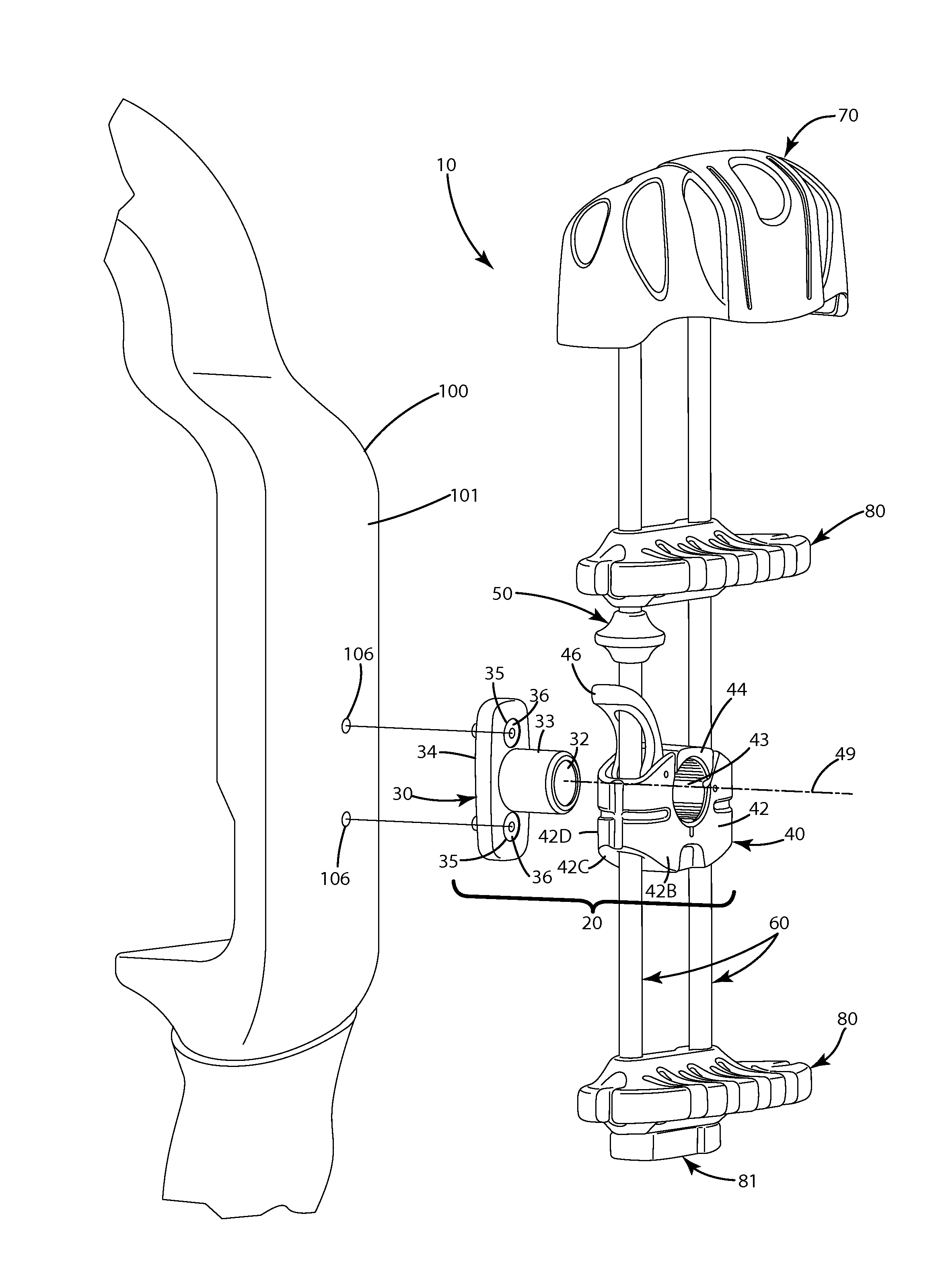
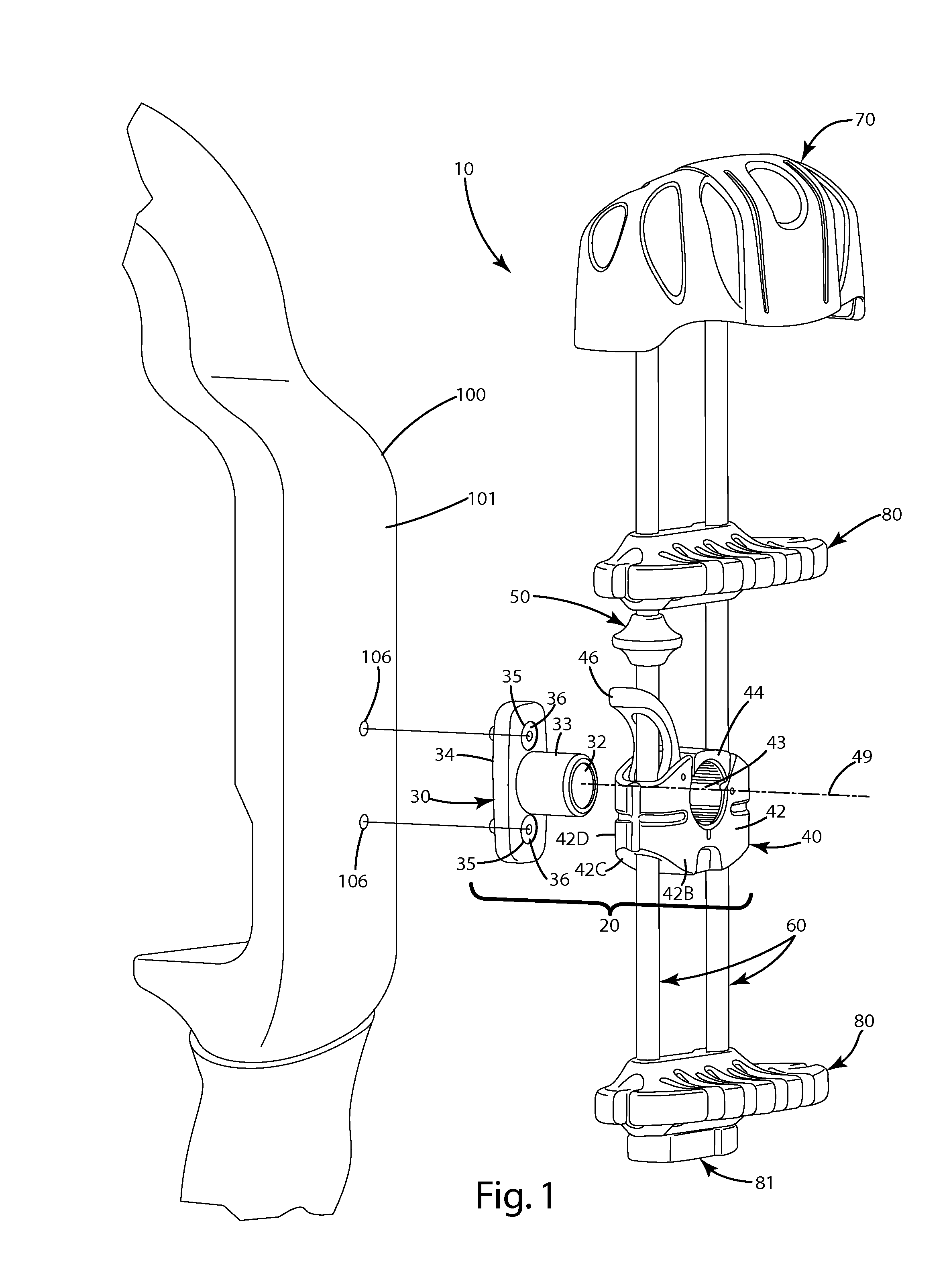
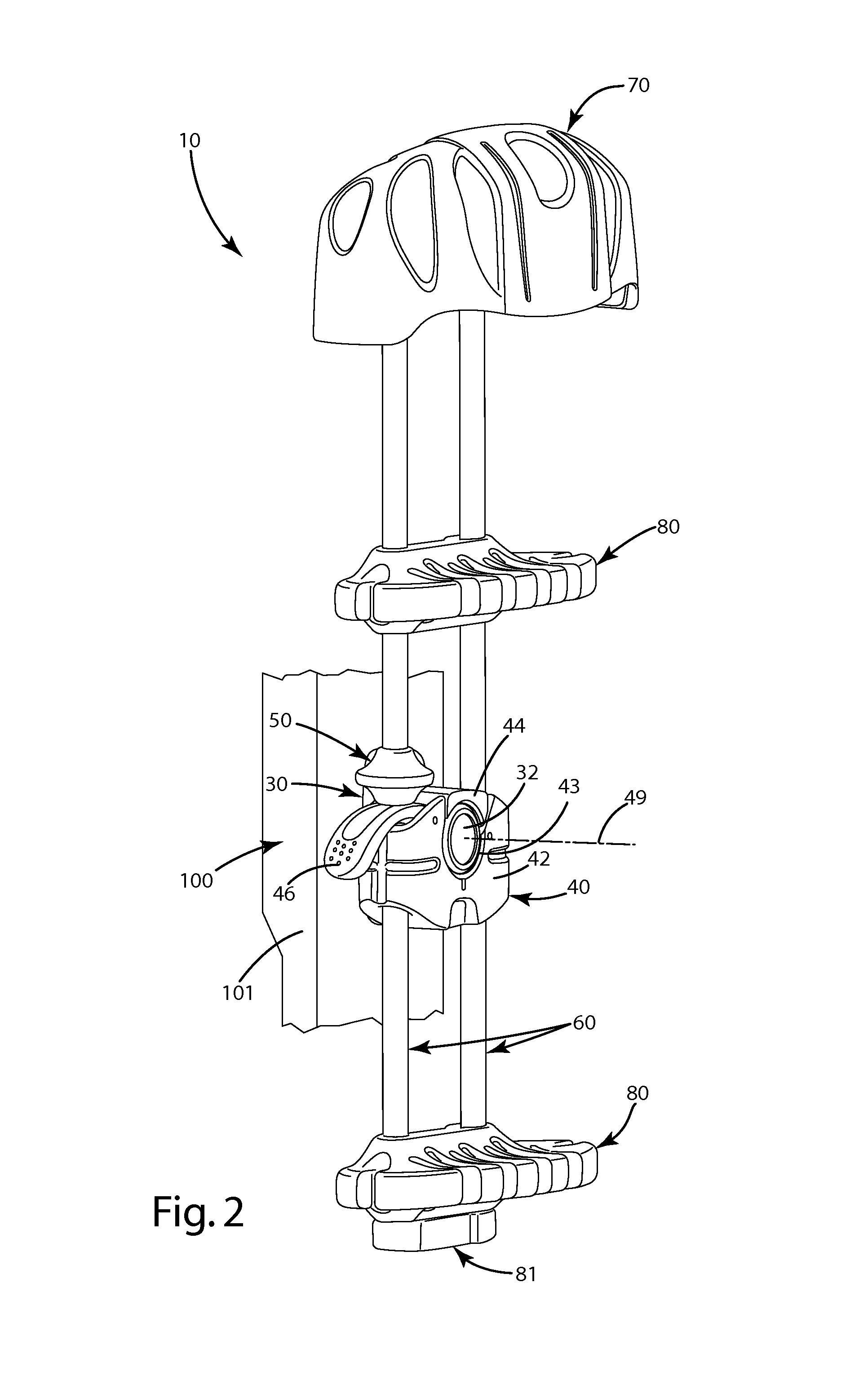
[0024]A current embodiment of the mounting system is illustrated in FIGS. 1-7 and generally designated 10. The mounting system 20 generally includes a primary element 30 and a secondary element 40. An optional secondary locking member 50 can be in close proximity to a portion of the secondary element 40. The secondary element also can be joined with supporting structures 60, which are generally shown or in the form of rods or bars extending above and below the mounting system 20. To the supporting structures 60, a hood 70 can be joined distal from the mounting system 20. One or more arrow holders 80 can be joined to the supporting structures 60 as shown as well.

[0025]Although shown in conjunction with a quiver mounted to an archery bow 100, and more particularly to an archery bow riser 101, the mounting system 20 can be used to mount the quiver, or any other items attached to the mounting system, directly to a variety of archery or hunting items, for example, a harness, a belt, a tr...


PUM

PropertyMeasurementUnit
cylindrical shapeaaaaaaaaaa
distanceaaaaaaaaaa
resilientaaaaaaaaaa

Abstract

An accessory mounting system for mounting a first object to a second object is provided. The system can be used to mount a quiver to an archery bow, or an archery or hunting accessory. The system can include a primary element having a projection that fits into an aperture defined by a secondary element. The secondary element can include a base, an engagement member and an actuator. The base can define at least a portion of an aperture. To the base, the engagement member can be moveably mounted to clampingly engage the projection when in the aperture. The actuator can be configured to actuate the engagement member, thereby fixedly mounting the secondary element to the projection. A related method of use also is provided.

Description

BACKGROUND OF THE INVENTION[0001]The present invention relates to devices that can be used to detachably mount objects in a fixed position relative to another object, and more particularly, to a quiver for an archery bow including an adjustable quick connect mounting system for detachably mounting a quiver to a structure such as a bow, a bow accessory, a belt, a tree stand, or other hunting or archery items.[0002]In the field of archery, quivers typically are used to conveniently and safely transport and hold one or more arrows at the ready for an archer. Many quivers include a simple mounting block that mounts directly to the riser of the bow. The mounting block is screwed directly to pre-tapped holes in the riser. Conventional quivers typically include a rod that extends upwardly from the mounting block to a hood. The rod also may include another arrow holder located a distance below the hood. Arrows are locked in the arrow holder, and associated field points or broadheads of the ...

Claims


Application Information

Patent Timeline
Patent Type & Authority Applications(United States)
IPC IPC(8): F41B5/06B23P11/00
CPCY10S224/916Y10T29/49826F41B5/066
Inventor LEE, SCOTT D.
Owner GRACE ENG
Why Eureka
Try Eureka