Hydraulically Operated Tool Including A Bypass Assembly

a bypass assembly and hydraulic operation technology, applied in the direction of manufacturing tools, portable power-driven tools, drilling pipes, etc., can solve the problems of high manufacturing cost, two settings, and poor durability of pvc-based dips

Active Publication Date: 2013-04-04
GREENLEE TEXTRON
View PDF3 Cites 13 Cited by
  • Summary
  • Abstract
  • Description
  • Claims
  • Application Information

AI Technical Summary

Problems solved by technology

The prior art insulates the metal valve body with a PVC-based dip, which tends to be inadequate to prevent the passage of heat generated by the high temperature hydraulic fluid.
In addition, the PVC-based dip is not very durable and is not easy to replace if the tool becomes damaged.
This presents a disadvantage in that only two settings are provided.
Pressure compensated flow control mechanisms are costly to manufacture.

Method used


Image

  • Hydraulically Operated Tool Including A Bypass Assembly
  • Hydraulically Operated Tool Including A Bypass Assembly
  • Hydraulically Operated Tool Including A Bypass Assembly

Examples


Embodiment Construction

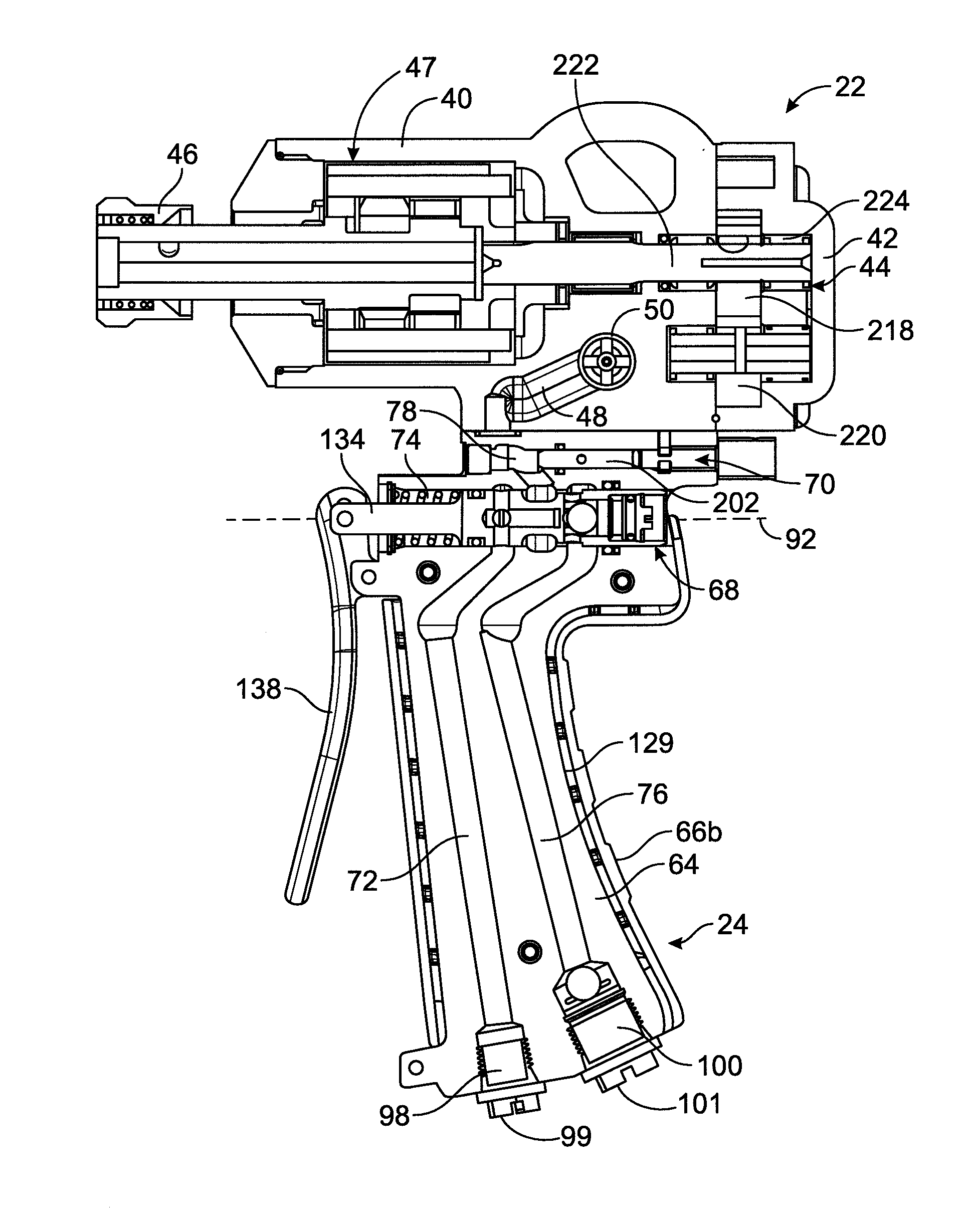
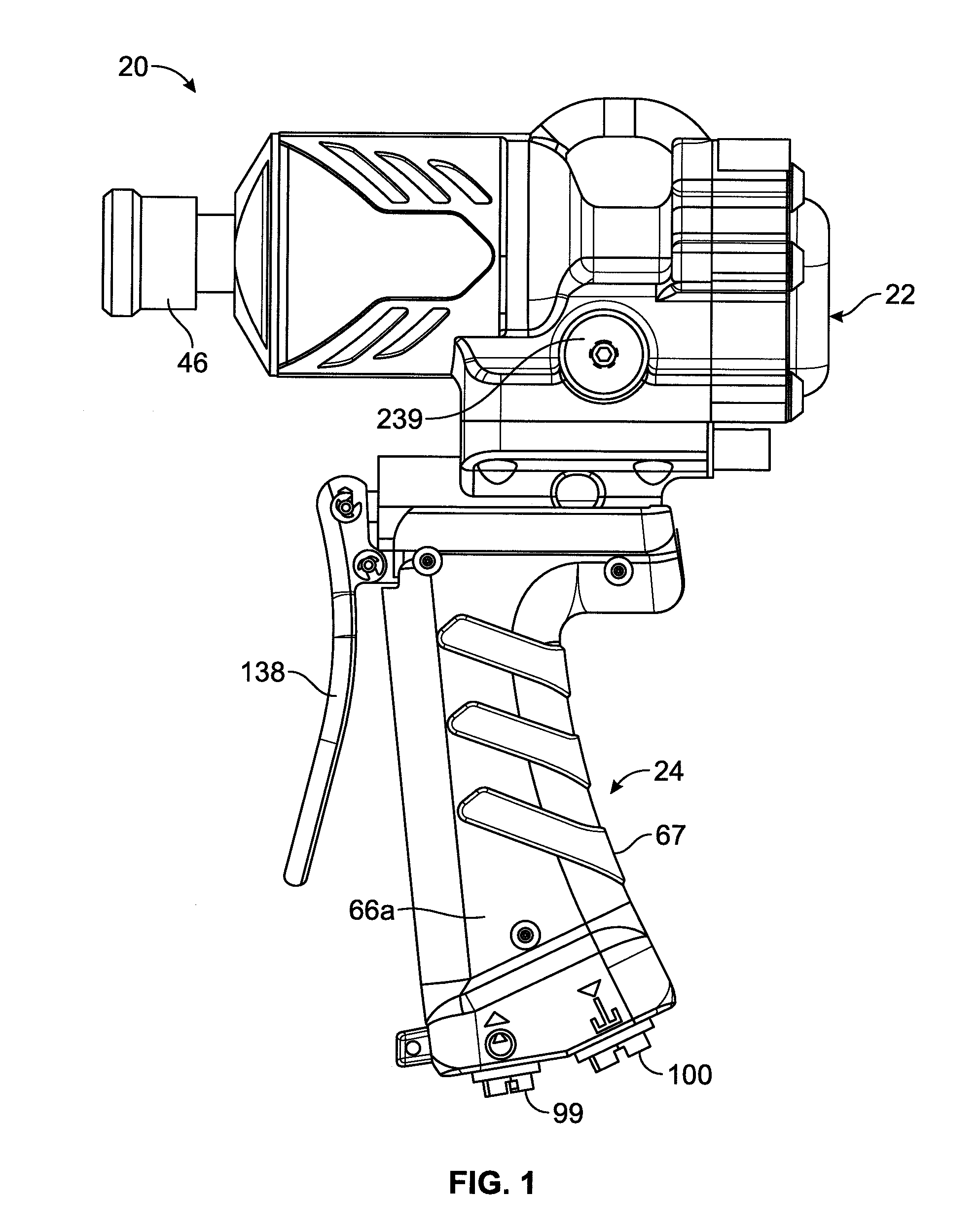
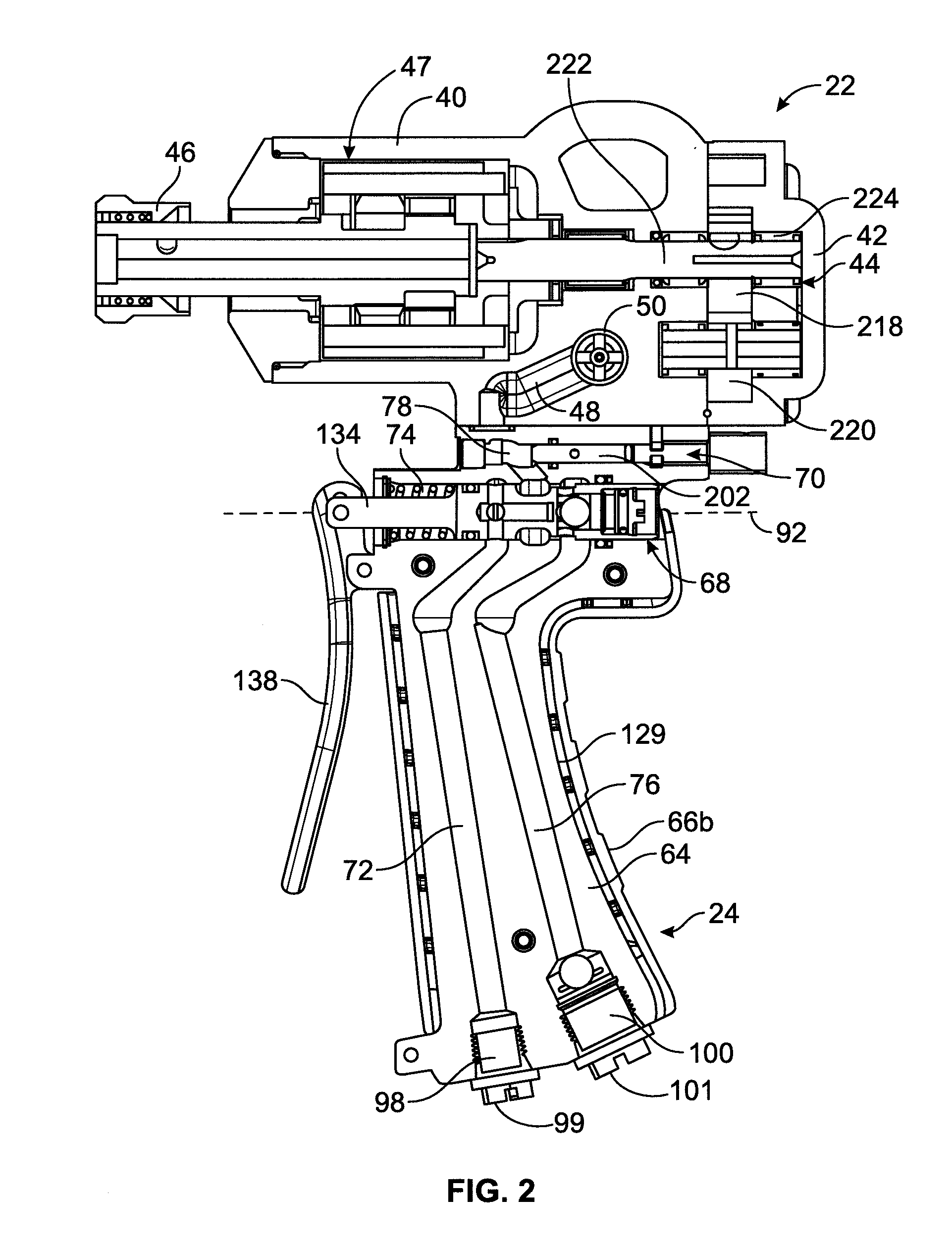
[0028]While the invention may be susceptible to embodiment in different forms, there is shown in the drawings, and herein will be described in detail, a specific embodiment with the understanding that the present disclosure is to be considered an exemplification of the principles of the invention, and is not intended to limit the invention to that as illustrated and described herein. Therefore, unless otherwise noted, features disclosed herein may be combined together to form additional combinations that were not otherwise shown for purposes of brevity.

[0029]A fluid-operated tool 20, such as a hydraulic wrench or drill, includes a fluid control system which provides for variable limitation of power output. The fluid control system provides multiple flow paths to provide for, among other things, selectable diversion of a portion of flow to a work unit assembly 22 of the tool 20, and reversing the direction of the work unit assembly 22. The tool 20 may be used by professional linemen ...


PUM


Abstract

A bypass assembly varies the hydraulic motor revolutions per minute (rpm) of a hydraulically driven tool, such as a wrench or a drill. This controls the torque of a driven mechanical mechanism, such as used on an impact wrench. The tool includes a body having a supply channel capable of being connected a source of fluid, a bypass spool channel in fluid communication with the supply channel, and a return channel in fluid communication with the bypass spool channel via a port and in fluid communication with the source. A bypass spool seats in the bypass spool channel. The bypass spool can be rotated to three discrete positions within the bypass spool channel to provide three different settings of revolutions per minute (rpm) of the gear motor.

Description

[0001]This application claims the domestic benefit of U.S. provisional application Ser. No. 61 / 541,674, filed on Sep. 30, 2011, which disclosure is herein incorporated by reference in its entirety.FIELD OF THE INVENTION[0002]The present invention particularly relates to a bypass assembly for varying the hydraulic motor revolutions per minute (rpm) of a hydraulically driven tool, such as a wrench or a drill, which controls the torque of a driven mechanical mechanism, such as used on an impact wrench.BACKGROUND OF THE INVENTION[0003]Existing hydraulic tools, such as hydraulic wrenches, generate heat as result of the use of high temperature hydraulic fluid passing through the tool. The user grips a grip which surrounds a metal valve body through which the high temperature hydraulic fluid passes. It is desirable to prevent the transfer of this heat to the user's hand. The prior art insulates the metal valve body with a PVC-based dip, which tends to be inadequate to prevent the passage o...

Claims


Application Information

Patent Timeline
Patent Type & Authority Applications(United States)
IPC IPC(8): B25F5/00B25B21/00
CPCB25F5/02B25B23/1453B25F5/008B25F5/005
Inventor TULLY, GERALD JONATHAN
Owner GREENLEE TEXTRON
Why Eureka
Try Eureka