Pressure Plate Assembly And Method For Power Transmission

a technology of pressure plate and assembly method, which is applied in the direction of power current collectors, electric vehicles, electric power, etc., can solve the problems of affecting the operation of the pressure plate, the rubber element loses its spring effect relatively quickly, and the rubber element cannot provide an adequate mounting of the contact shoe unit, etc., to achieve reliable operation

Active Publication Date: 2013-04-04
SCHUNK BAHN UND INDTECHN
View PDF25 Cites 22 Cited by
  • Summary
  • Abstract
  • Description
  • Claims
  • Application Information

AI Technical Summary

Benefits of technology

[0010]By using a helical spring for the spring unit it is possible to generate a comparatively large pressing force. A helical spring may be pre-tensioned over a prolonged period of time without the danger of losing its springiness. Compared to a rubber element therefore, replacement of the helical spring is required less often. Furthermore, by using a helical spring for the spring unit, it is possible to achieve a much more stable positioning of the contact shoe unit relative to the current rail. The contact shoe unit is then exposed to fewer undesirable vibrations and movements.
[0022]Furthermore the shaft may comprise a clamping section which may be fixed to a clamping element of the holding unit. The clamping element may, for example, be implemented as a clip and may encompass a circumference of the clamping section. Tightening the clip, for example by means of a screw, has the effect of creating a frictional connection between a shaft and the holding unit. Thus by applying a radial force to the shaft it is easy to create a connection between shaft and holding unit.

Problems solved by technology

The disadvantage when using a rubber element as a spring unit consists in that the rubber element loses its spring effect relatively quickly and requires frequent replacement.
Furthermore the rubber element is unable to provide for an adequate mounting of the contact shoe unit relative to the current rail.
It is therefore possible that during operation of the current rail the sliding contact is interrupted if the contact shoe unit moves in an undesirable manner or that a sufficient pressing force fails to be applied upon the current rail.

Method used


Image

  • Pressure Plate Assembly And Method For Power Transmission
  • Pressure Plate Assembly And Method For Power Transmission
  • Pressure Plate Assembly And Method For Power Transmission

Examples


Embodiment Construction

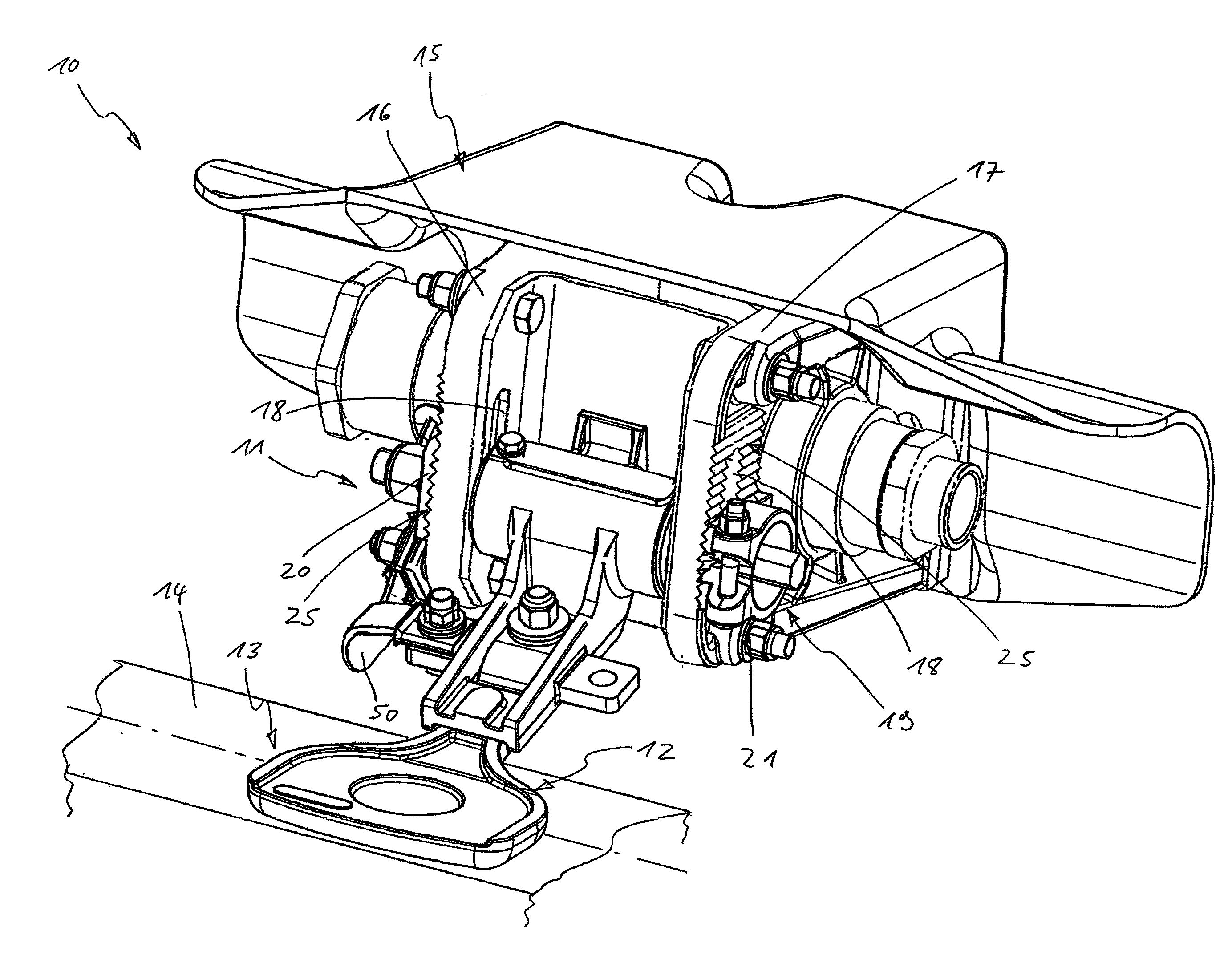
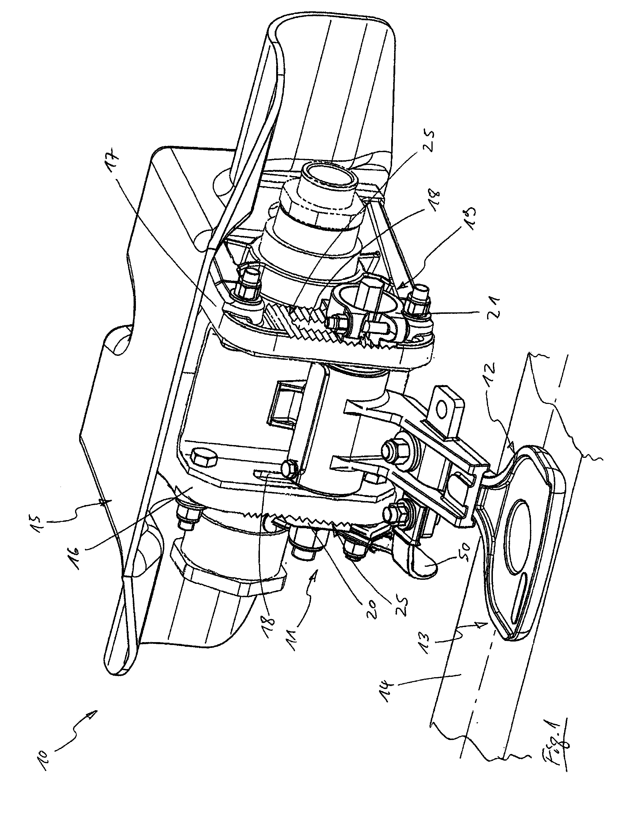
[0030]FIG. 1 shows a current collector 10 with a pressing device 11 and a contact shoe unit 12. A sliding contact 13 is formed by pressing the contact shoe unit 12 of the current collector 10 against a current rail 14 of which a section is shown here. The current collector further comprises a carrier device 15 formed essentially of two vertically arranged parallel plates 16 and 17. A longitudinal groove 18 is formed in each of the plates 16 and 17. The pressing device 11 comprises a holding unit 19 for connection with the carrier device 15. The holding unit 19 further comprises a first clamping element 20 and a second clamping element 21. Both clamping elements 20 and 21 comprise a groove-shaped locking profile 24 on a supporting surface 22, 23, which locking profile matches a locking profile 25 on the plates 16 and 17. This enables the clamping elements 20 and 21 to be positioned and clamped fast exactly opposite the plates 16 and 17 without the clamping elements 20 and 21 becoming...


PUM


Abstract

A pressing device for a current collector moves a contact shoe unit is movable relative to a current rail. The pressing device includes a rocker unit and a spring unit. The spring unit having a helical spring rotatably biasing rocker unit is rotatable such that the contact shoe unit is movable into a sliding contact position in only one direction spring unit.

Description

CROSS REFERENCE TO RELATED APPLICATION[0001]The present application claims the benefit of European Patent Application No. 11007929.0 filed Sep. 29, 2011, which is fully incorporated herein by reference.STATEMENT REGARDING FEDERALLY SPONSORED RESEARCH OR DEVELOPMENT[0002]Not applicable.FIELD OF THE INVENTION[0003]The invention relates to a pressing device for a current collector, a current collector and a method for the transfer of energy from a current rail to a vehicle, wherein the pressing device is designed such that a contact shoe unit of the current collector is movable relative to the current rail by means of the pressing device and is pressable in a sliding contact position against the current rail with a pressing force for producing a sliding contact, wherein the pressing device comprises a rocker unit, wherein the rocker unit is designed so as to be rotatable such that the contact shoe unit, by creating a pressing force, is movable in only one direction into a sliding conta...

Claims


Application Information

Patent Timeline
Patent Type & Authority Applications(United States)
IPC IPC(8): B60L5/38
CPCB60L5/08B60L2200/26B60L5/38
Inventor SOMMER, MARTIN
Owner SCHUNK BAHN UND INDTECHN
Why Eureka
Try Eureka