Energy storage cell and energy storage module

Inactive Publication Date: 2013-04-04
NISSAN DIESEL MOTOR CO
View PDF2 Cites 9 Cited by
  • Summary
  • Abstract
  • Description
  • Claims
  • Application Information

AI Technical Summary

Benefits of technology

[0010]The electrode terminals 112 are bent for being easily joined, but a projecting length E of the electrode terminals 112, which is the length of parts drawn out from the containers of the energy storage cells 100, accordingly becomes longer. Thus, a large space is necessary outside the container 111 to electrically connect the energy storage cells 1

Problems solved by technology

In the energy storage module M100 constituted by the energy storage cells 100, there are many restrictions in the arrangement and layout of the energy storage cells 100 due to a connection structure for electrically connecting the energ

Method used


Image

  • Energy storage cell and energy storage module
  • Energy storage cell and energy storage module
  • Energy storage cell and energy storage module

Examples


first embodiment

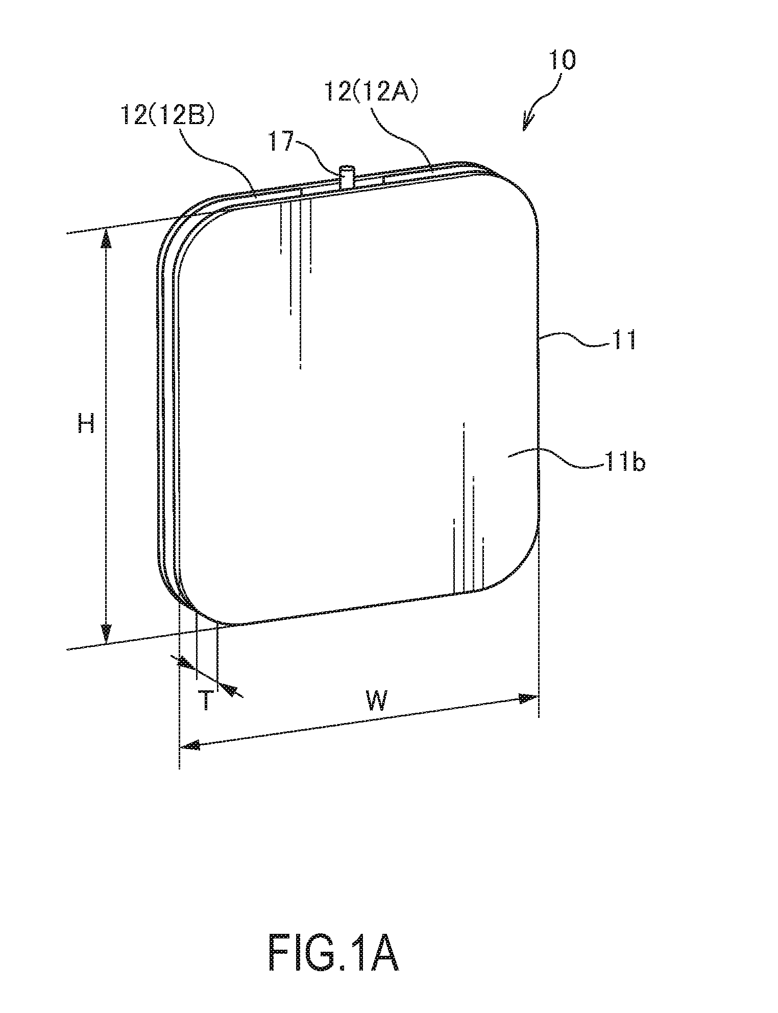
[0038]First, with reference to FIGS. 1A to 5, an energy storage cell 10 according to the present invention is described. In the following description, W, H and T denote the width, height and thickness of the energy storage cell 10 as shown in FIG. 1A. The following description is made with a plane bisecting the width W of the energy storage cell 10 as a plane A and a plane bisecting the height H as a plane B as shown in FIG. 5.

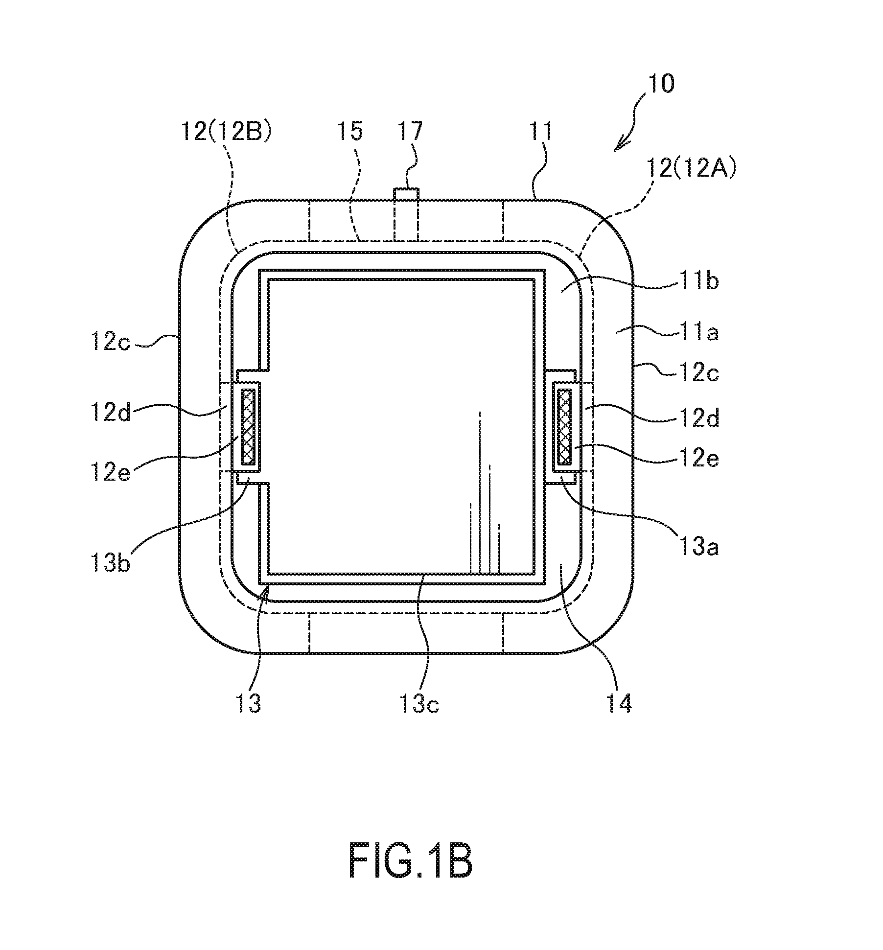
[0039]The energy storage cell 10 is an electric double-layer capacitor. As shown in FIG. 1B, the energy storage cell 10 includes an energy storage part 13 for storing electric charges, a container 11 for housing the energy storage part 13 and a pair of electrode terminals 12 through which electric charges are charged into and discharged from the energy storage part 13.

[0040]As shown in FIG. 1B, the energy storage part 13 is a laminated body in which a positive electrode 13a, a negative electrode 13b and a separator 13c interposed between the positive electrode...

second embodiment

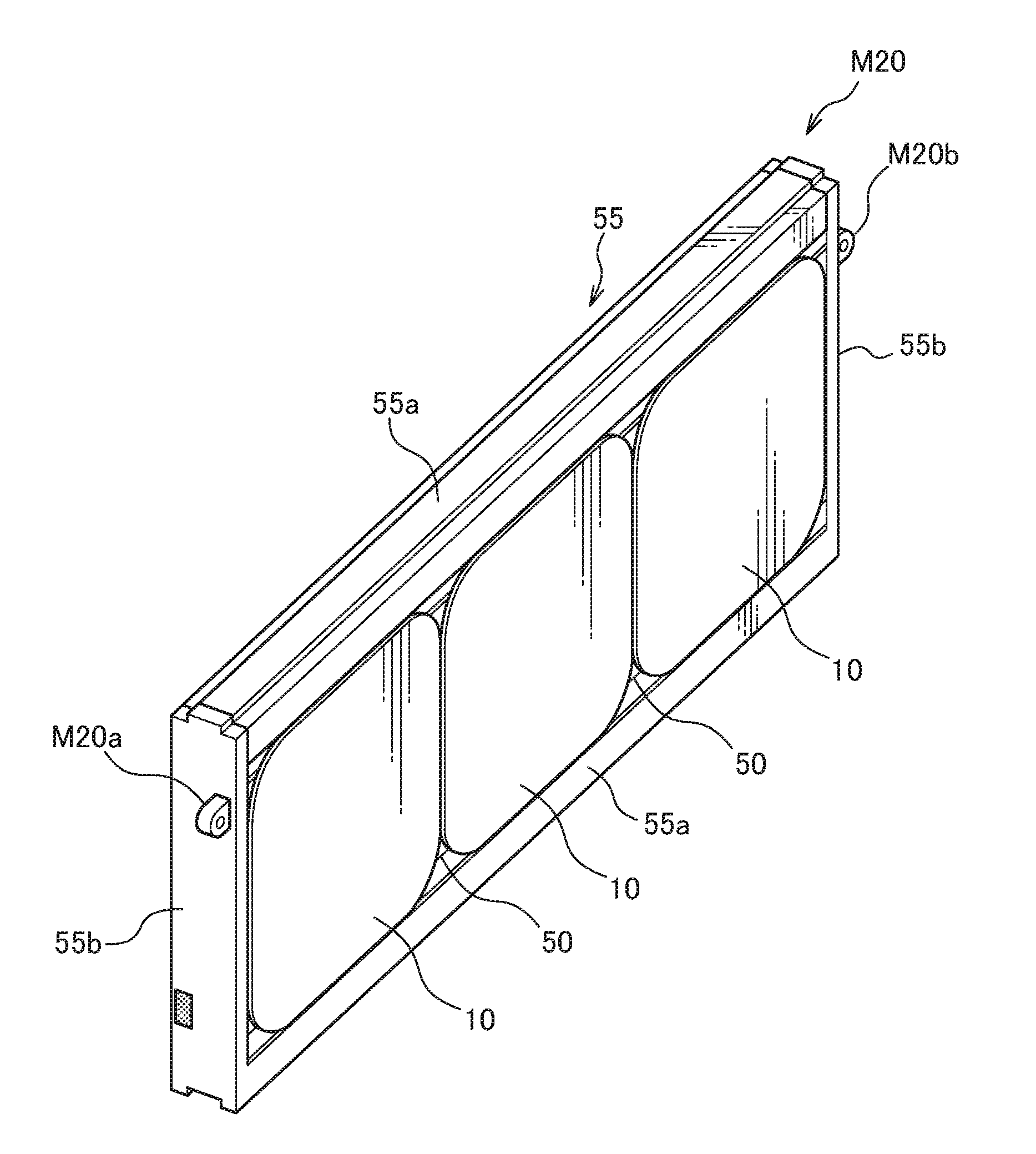
[0062]Next, an energy storage cell 20 according to the present invention is described with reference to FIGS. 6 to 8. In each embodiment described below, configurations similar to the embodiment described above are denoted by the same reference signs and repeated description is omitted as appropriate. The following description is made with a plane bisecting a thickness T of the energy storage cell 20 as a plane C as shown in FIG. 8.

[0063]The energy storage cell 20 is an electric double-layer capacitor. As shown in FIG. 6, the energy storage cell 20 includes an energy storage part 13 for storing electric charges, a container 11 for housing the energy storage part 13 and a pair of electrode terminals 22 through which electric charges are charged into and discharged from the energy storage part 13.

[0064]The electrode terminals 22 include a positive electrode terminal 22A connected to a positive electrode 13a of the energy storage part 13 and a negative electrode terminal 22B connected ...

third embodiment

[0070]Next, an energy storage cell 30 according to the present invention is described with reference to FIG. 9.

[0071]The energy storage cell 30 is an electric double-layer capacitor. As shown in FIG. 9, the energy storage cell 30 includes an energy storage part 13 for storing electric charges, a container 11 for housing the energy storage part 13 and a pair of electrode terminals 32 through which electric charges are charged into and discharged from the energy storage part 13.

[0072]The electrode terminals 32 include a positive electrode terminal 32A connected to a positive electrode 13a of the energy storage part 13 and a negative electrode terminal 32B connected to a negative electrode 13b of the energy storage part 13. The positive electrode terminal 32A and the negative electrode terminal 32B are respectively provided on a pair of mutually facing side surfaces of the container 11.

[0073]When a pair of groove parts 15 are respectively formed on a pair of facing side surfaces of the...


PUM


Abstract

An energy storage cell includes an energy storage part for storing electric charges, a container for housing the energy storage part, and a pair of electrode terminals connected to the energy storage part and exposed to the outside of the container. The container is formed to have a thick polygonal outer shape and a groove part linearly extending in a direction perpendicular to a thickness direction is provided in each of a pair of mutually facing side surfaces of the polygonal shape. Each of the electrode terminals includes a base end part connected to a corresponding polarity of the energy storage part in the container and an exposed part exposed to the outside of the container, and the exposed part is formed along an inner side of the groove part.

Description

FIELD OF THE INVENTION[0001]The present invention relates to an energy storage cell and an energy storage module constituted by a plurality of energy storage cells.BACKGROUND OF THE INVENTION[0002]JP2003-272972A, JP2006-108380A, JP2003-272966A, JP3869183B, JP2006-338934A, JP2008-204985A, JP2002-353078A and JP2005-190885A propose an electric double-layer capacitor, a lithium-ion battery and the like as an energy storage cell which is quickly rechargeable and has a long charge / discharge cycle life.[0003]An example is described with reference to FIG. 22. An energy storage cell 100 is an electric double-layer capacitor. The energy storage cell 100 includes an energy storage part for storing electric charges and a container 111 for containing the energy storage part.[0004]The energy storage part is a laminated body composed of a positive electrode, a negative electrode and a separator interposed between the positive electrode and the negative electrode. The positive electrode and the neg...

Claims


Application Information

Patent Timeline
IPC IPC(8): H01G9/00H01G2/04H01G11/00H01G11/10H01M50/103H01M50/505H01M50/553
CPCH01G2/04H01G9/155H01G11/10H01G11/74H01G4/224H01M2/0207H01M2/204H01M2/30Y02E60/13H01G11/78Y02E60/10H01M50/553H01M50/505H01M50/103
Inventor KOBAYASHI, SHIGEMI
Owner NISSAN DIESEL MOTOR CO
Why Eureka
Try Eureka