Clothing Steam Ironing Apparatus

a technology of ironing apparatus and cloth steam, which is applied in the direction of chemistry apparatus and processes, cleaning using liquids, and other washing machines, etc. it can solve the problems of hazard to human health, difficulty in ironing operation, and prior ironing apparatus in hanging arrangement, so as to improve ironing efficiency and effect, and facilitate the user to iron clothing. , the effect of enhancing the ironing efficiency

Active Publication Date: 2013-04-11
ZHANG YUNFENG
View PDF8 Cites 16 Cited by
  • Summary
  • Abstract
  • Description
  • Claims
  • Application Information

AI Technical Summary

Benefits of technology

[0021]Due to the presence of the air suction holes, the ironing side of the clothing will stick to the ironing panel when the ironing panel contacts the clothing to be ironed. The operator could move the ironing apparatus when ironing the clothing, so it is convenient for the user to iron the clothing; meanwhile, the clothing could be ironed smooth. Therefore, both of the ironing efficiency and effect are enhanced.
[0022]By combining air suction holes and dust collection device, the clothing, as well as bedding, sofa and seat cushion could be dusted when the ironing panel of the ironing head contacts them. Furthermore, by virtue of the high temperature of the steam, the ironing apparatus of present invention further provide a sterilization function, so that the hazard to health of human, especially old people and children, incurred by the dust, pollen, acarus and other pollutants might be reduced. Thus, the clothing will undergo a cleaning and sterilizing process when being ironed by the ironing apparatus of present invention.

Problems solved by technology

However, some disadvantages exist in prior ironing apparatus in hanging arrangement.
For example, because there is no support at the back side of the hanging clothing, the ironing operation is a bit difficult and the clothing will not be ironed as smooth as it would be by ironing with pressure (such as, the back side of the clothing is supported by a rigid body).
Thus the ironing efficiency and effect may not satisfy the increasing demand nowadays.
In addition, prior clothing steam ironing apparatus could be only used in clothing ironing, and could not perform other useful function like dust elimination.

Method used


Image

  • Clothing Steam Ironing Apparatus
  • Clothing Steam Ironing Apparatus
  • Clothing Steam Ironing Apparatus

Examples


first embodiment

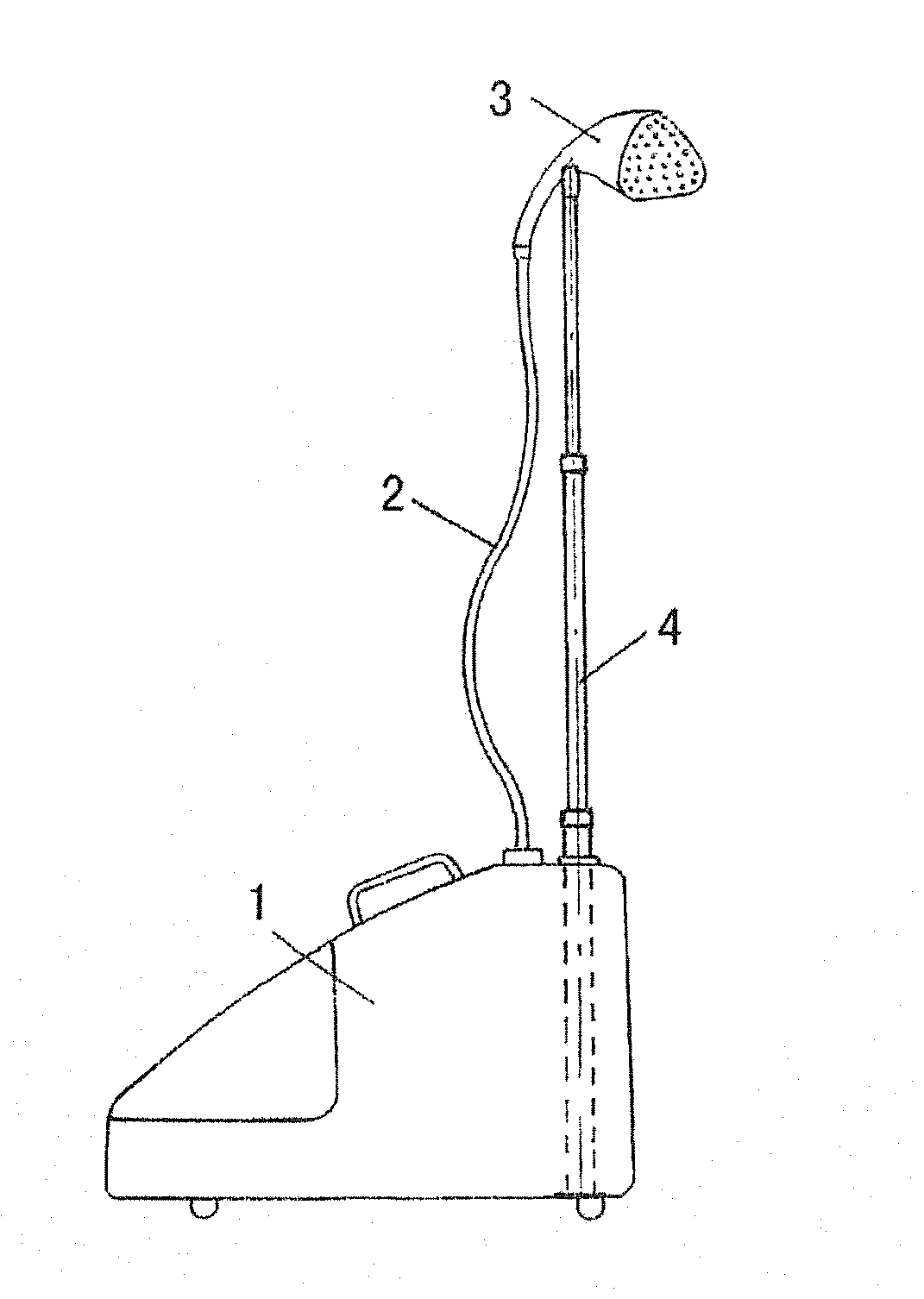
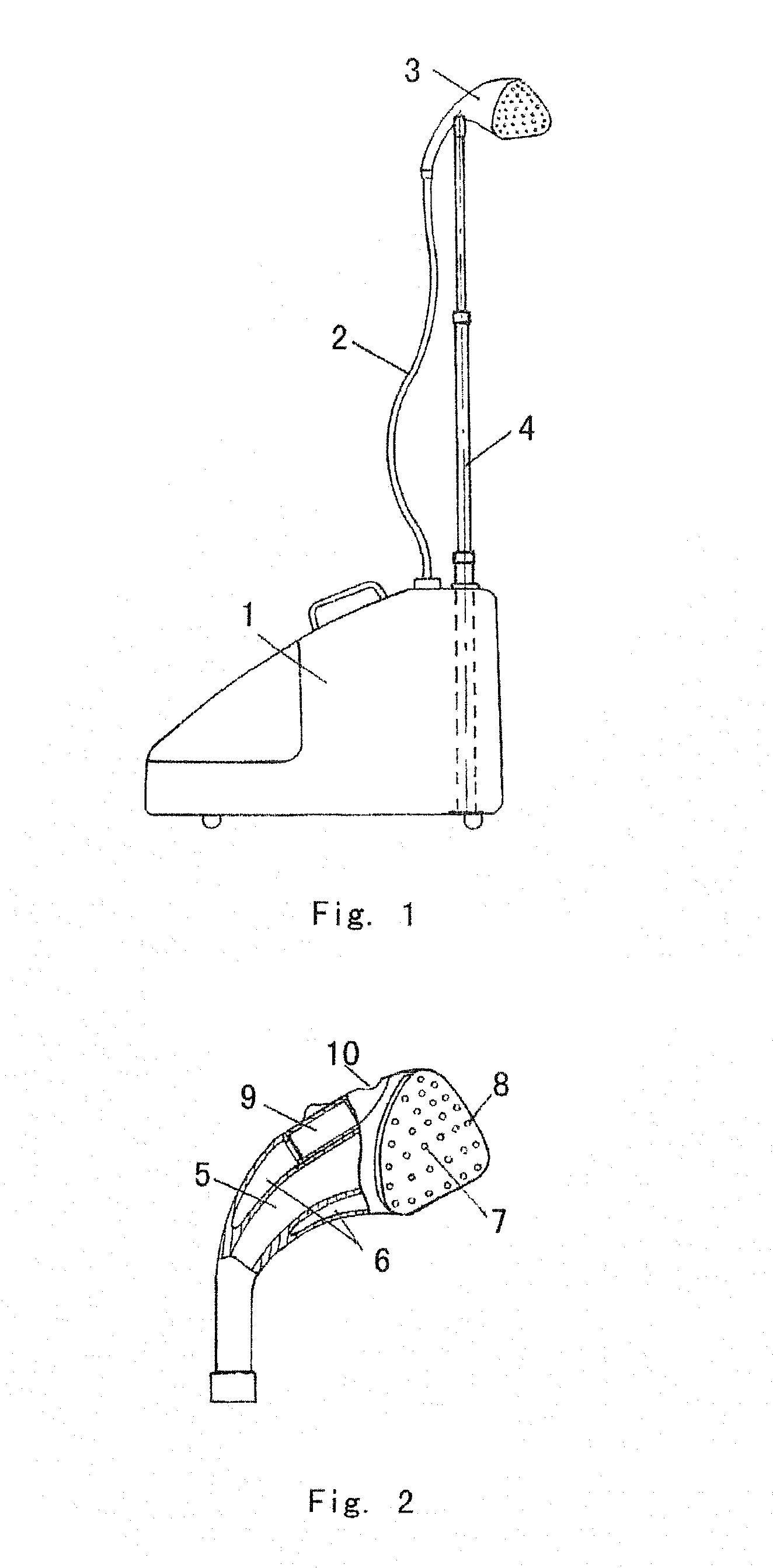
[0032]As illustrated in FIGS. 1, 2, the clothing steam ironing apparatus according to present invention comprises an ironing component 3 which includes an ironing panel (better seen in FIG. 2). Steam ejection holes 7 and suction holes 8 are provided in the ironing panel, and during use, the steam is ejected from the steam ejection holes 7 to iron the clothing while the suction holes 8 inhale air to generate a sucking force to the clothing.

[0033]In clothing steam ironing apparatus according to present invention, due to the sucking force provided by the suction holes 8, the side of the clothing being ironed is stuck to the ironing panel closely. The operator could move ironing component while ironing the clothing, which is convenient for the user on the one hand, and on the other hand, the fabric of the clothing could be ironed smooth. Therefore, both of the ironing efficiency and effect are enhanced.

[0034]In prefer embodiment of present invention, as illustrated in FIG. 2, the ironin...

second embodiment

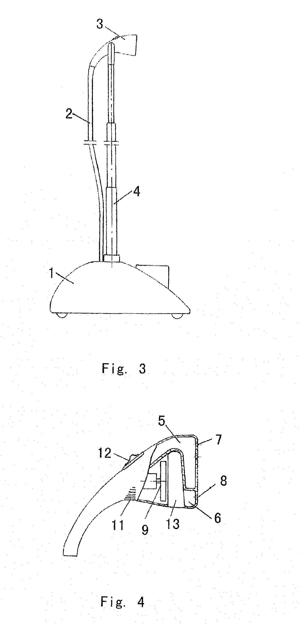
[0042]FIGS. 3, 4 illustrate present invention. In FIGS. 3, 4 same elements are denoted by same reference sign, for the purpose of clarity, the description about same elements will not be repeated.

[0043]FIG. 4 illustrates the control switch 12 of the fan. According to the second embodiment of present invention, the configuration of the steam chamber 5 and the air suction chamber 6 is different from that in the first embodiment. More specifically, though the steam chamber 5 and the air suction chamber 6 are separated from each other too, as illustrated in FIG. 4, the area that the steam chamber 5 contacts the ironing panel is much larger than the area that the air suction chamber 6 contacts the ironing panel. Correspondingly, the locations of the steam ejection holes 7 and suction holes 8 are also different from that in the first embodiment. In the second embodiment, the steam ejection holes 7 and the suction holes 8 are formed at the upper side and the lower side of the ironing panel...

third embodiment

[0047]Besides, according to present invention, a suction adjusting valve 15 is provided in the ironing component 3. The valve 15 could be configured as a ring body and mounted at the lower end of the ironing component 3. An air inhaling hole is formed in the ring body of the valve 15, and a corresponding air inhaling hole communicating with the air suction chamber 6 could be provided in the ironing component 3. By rotating the ring body, the air flow through the two air inhaling holes could be adjusted, up to the maximum flow rate or be reduced to zero (closed up). Thus the sucking force acted on the clothing to be ironed could be adjusted to meet various ironing requirements for different materials of the clothing.

[0048]Preferably, a filter 16 is provided in the housing of the mount 1 and fits with the air outlet 10, so that the air discharged by the fan 9 is filtered by the filter 16. To facilitate the cleaning work, the filter 16 preferably is removably mounted in the housing of ...


PUM

PropertyMeasurementUnit
suck forceaaaaaaaaaa
velocityaaaaaaaaaa
pressureaaaaaaaaaa

Abstract

Disclosed is a clothing steam ironing apparatus, comprising an ironing component (3) with an ironing panel, steam ejection holes (7) for ejecting steam to iron a clothing and air suction holes (8) for generating a suck force to the clothing are provided in the ironing panel.

Description

BACKGROUND OF THE INVENTION[0001]1. Field of Invention[0002]The present invention relates to a clothing steam ironing apparatus, particularly to one suitable for ironing clothing while the clothing is hanging.[0003]2. Description of the Related Art[0004]Steam ironing for clothing has advantages of high efficiency, good ironing effect, and no bad influence to the surface and texture of the clothing. Further, due to elimination of the need of a flat bench, hanging arrangement for steam ironing is especially convenient.[0005]However, some disadvantages exist in prior ironing apparatus in hanging arrangement. For example, because there is no support at the back side of the hanging clothing, the ironing operation is a bit difficult and the clothing will not be ironed as smooth as it would be by ironing with pressure (such as, the back side of the clothing is supported by a rigid body). Thus the ironing efficiency and effect may not satisfy the increasing demand nowadays.[0006]In addition...

Claims


Application Information

Patent Timeline
Patent Type & Authority Applications(United States)
IPC IPC(8): D06F75/20
CPCD06F73/00D06F87/00D06F75/30D06F75/12D06F75/20
Inventor ZHANG, YUNFENG
Owner ZHANG YUNFENG
Why Eureka
Try Eureka