Pneumatic packaging apparatus

Active Publication Date: 2013-04-11
YU CHEN HSIU MAN
View PDF7 Cites 5 Cited by
  • Summary
  • Abstract
  • Description
  • Claims
  • Application Information

AI Technical Summary

Benefits of technology

[0008]To use the pneumatic packaging apparatus of this invention, firstly, have two ends of a packaging strap oppositely inserted through a packaging fastener to be overlapped on the base plate and positioned between the roller and the driving wheel. Next, press down the first press key to open the first valve body to let external high pressure gas flow into the pneumatic motor through the air intake to enable the pneumatic motor to drive the driving wheel to rotate for actuating the two ends of the packaging strap to be moved oppositely and pulled

Problems solved by technology

However, packaging apparatuses at the present time are mostly operated manually so it is necessary to take much time and physical strength for pulling tight the packaging strap.
Thus, users doing such packaging work for a long period of time are apt to f

Method used


Image

  • Pneumatic packaging apparatus
  • Pneumatic packaging apparatus
  • Pneumatic packaging apparatus

Examples


Embodiment Construction

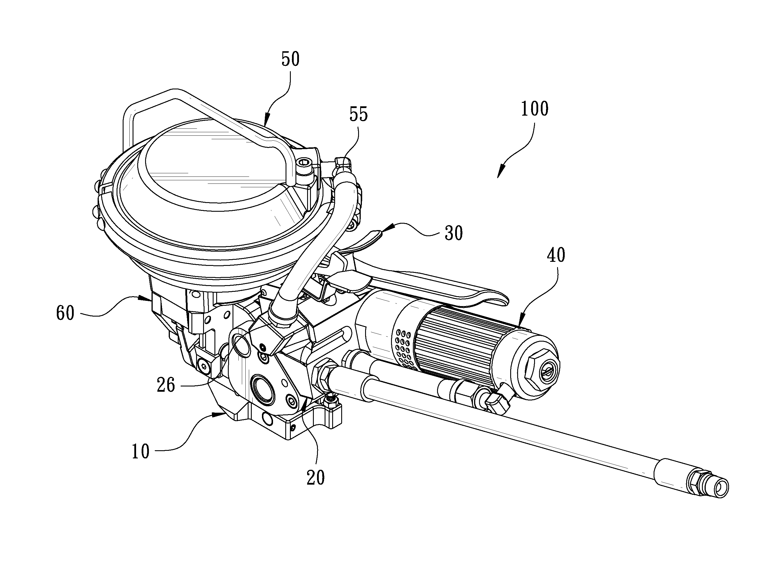
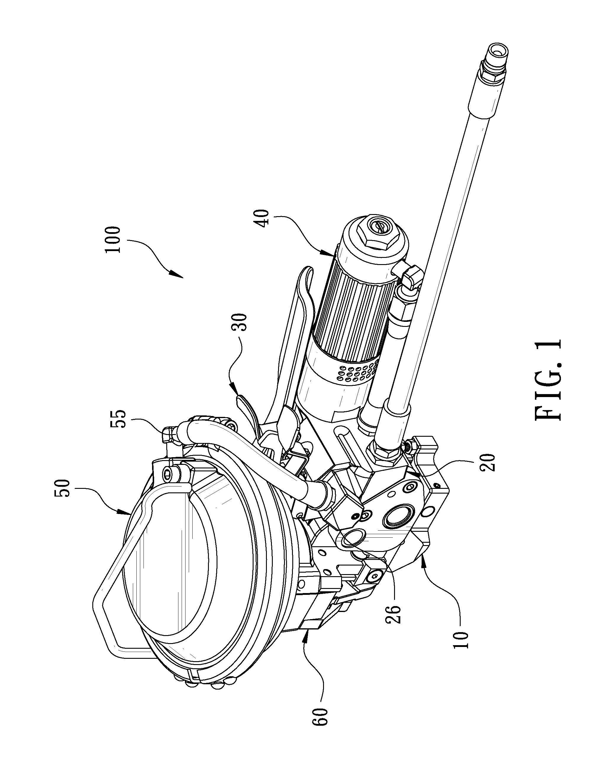
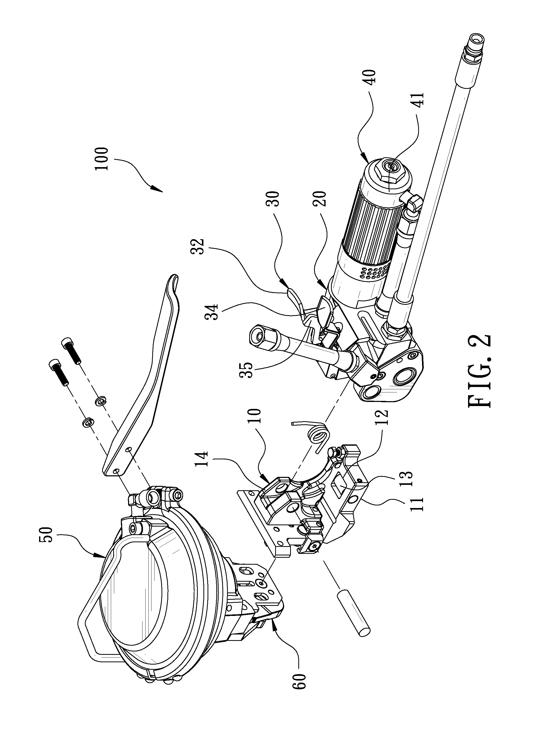
[0024]A preferred embodiment of a pneumatic packaging apparatus 100 in the present invention, as shown in FIGS. 1-8, includes a fixed base 10, a valve seat 20. a control unit 30. a driving unit 40, a pressure cylinder unit 50 and a chuck unit 60 as main components combined together.

[0025]The fixed base 10 is provided with a base plate 11 formed with a front end 111 and an opposite rear end 112 and having its topside longitudinally bored with at least one insert hole 12 having at least one roller 13 pivotally assembled therein. In this preferred embodiment, the base plate 11 is longitudinally bored with one insert hole 12 pivotally set therein with one roller 13 that is shaped as a column, whose pivot is perpendicular to the lengthwise side of the base plate 11. Further, the base plate 11 of the fixed base 10 has one side provided with a fixed block 14 protruding up vertically.

[0026]The valve seat 20 is pivotally mounted at one side of the fixing block 14, facing the rear end 112 of ...


PUM


Abstract

A pneumatic packaging apparatus includes a fixed base provided thereon with a pressure cylinder unit connected with a chuck unit. The fixed base is further mounted with a valve seat combined thereon with a driving unit and a control unit. The control unit is able to receive external high pressure gas and control the high pressure gas to flow to the driving unit and to the pressure cylinder unit to let the driving unit and the pressure cylinder unit driven by air pressure to automatically pull tight the packaging strap and firmly squeeze the packaging fastener for fixing the packaging strap in place. Thus, the pneumatic packaging apparatus of this invention can assist users to complete packaging work with quickness, able to elevate efficiency of the packaging work.

Description

BACKGROUND OF THE INVENTION[0001]1. Field of the Invention[0002]This invention relates to a pneumatic packaging apparatus.[0003]2. Description of the Prior Art[0004]Generally, when transported, goods are usually tied up by means of packaging straps so as to prevent the goods from rocking and falling down on the way of transportation. When goods are to be tied up, a packaging strap is first wound around the peripheral side of the goods and two free ends of the packaging strap are oppositely inserted through a packaging fastener and secured on a packaging apparatus. Subsequently, the two free ends of the packaging strap will be oppositely moved forward by the packaging apparatus for pulling tight the packaging strap and then, the packaging fastener will be squeezed by the packaging apparatus for fixing the packaging strap in place, thus finishing binding the goods.[0005]However, packaging apparatuses at the present time are mostly operated manually so it is necessary to take much time...

Claims


Application Information

Patent Timeline
IPC IPC(8): B65B13/24
CPCB65B13/345B65B13/22
Inventor YU CHEN, HSIU-MAN
Owner YU CHEN HSIU MAN
Why Eureka
Try Eureka