Switching regulator and electronic device incorporating same

a technology of switching regulator and electronic device, which is applied in the direction of power conversion system, dc-dc conversion, instruments, etc., can solve the problems of increasing chip size and current consumption, degrading the accuracy of output voltage, and high consumption of battery power at very high rates

Active Publication Date: 2013-04-11
NISSHINBO MICRO DEVICES INC
View PDF7 Cites 25 Cited by
  • Summary
  • Abstract
  • Description
  • Claims
  • Application Information

AI Technical Summary

Benefits of technology

[0030]In one aspect of this disclosure, there is a provided novel switching regulator to convert an input voltage into a predetermined output voltage. The switching regulator includes an input terminal; an output terminal; a first switching element; a second switching element; a switching-time control circuit; a first comparator; a switching-element control circuit. The input voltage is input to the input terminal. The output terminal outputs the output voltage. The first switching element is connected between the input terminal and the output terminal. The second switching element is connected between the output terminal and ground. The switching-time control circuit generates a first switching-time control signal indicating finish timing of an ON-period of the first switching element when a first time period, corresponding to a ratio of a length of the ON-period of the first switching element to a sum of lengths of ON-periods of the first switching element and the second switching element, has elapsed from respective reset-release tim...

Problems solved by technology

The applications themselves tend to consume battery power at very high rates, and as a result, a power supply circuit whose external components are compact while at the same time able to handle large currents and low output voltages is needed.
In addition, the time-averaged voltage VOUTa of the output voltage VOUT cannot be kept constant, which degrades the accuracy of the output voltage.
With this configuration, th...

Method used


Image

  • Switching regulator and electronic device incorporating same
  • Switching regulator and electronic device incorporating same
  • Switching regulator and electronic device incorporating same

Examples


first embodiment

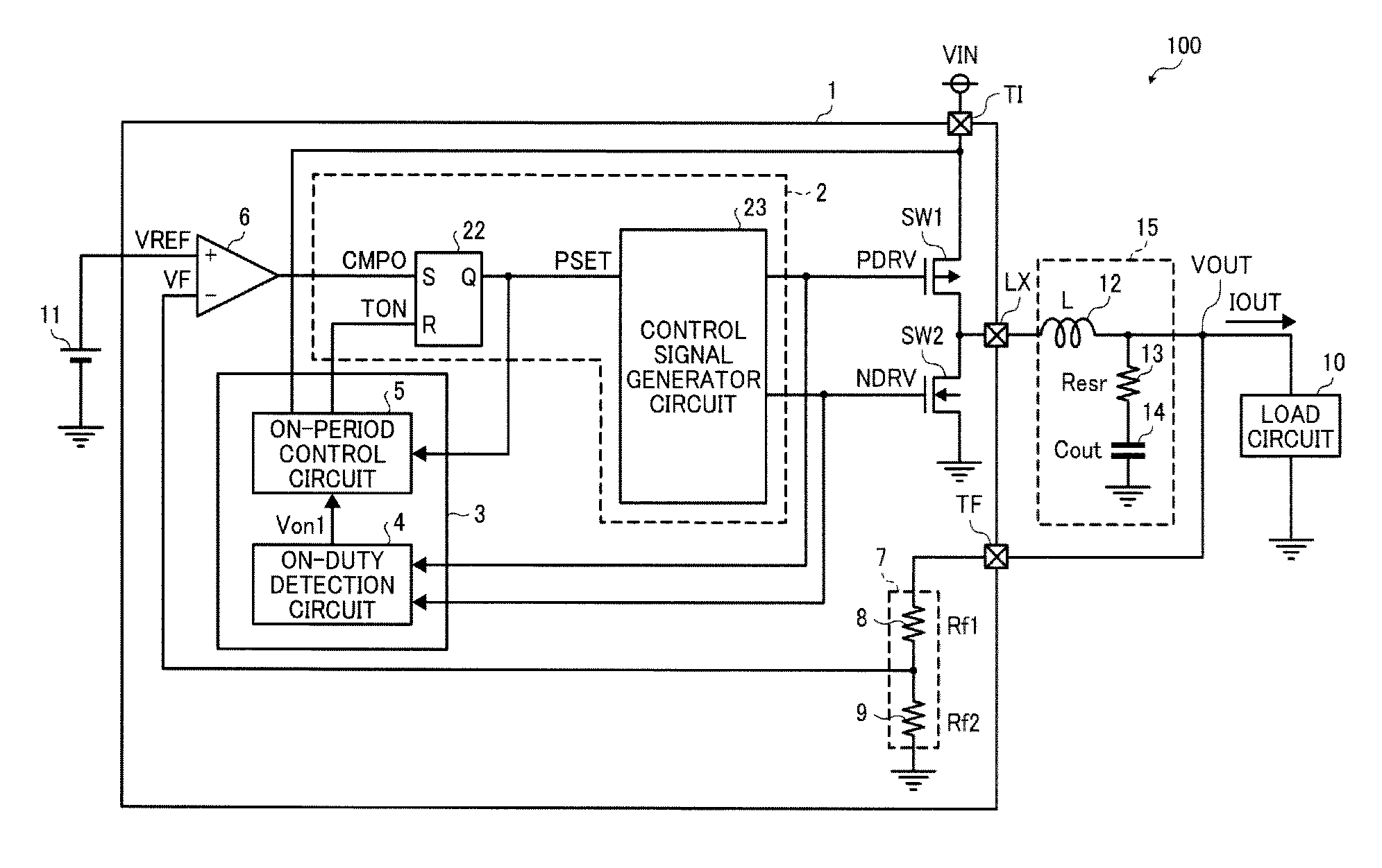
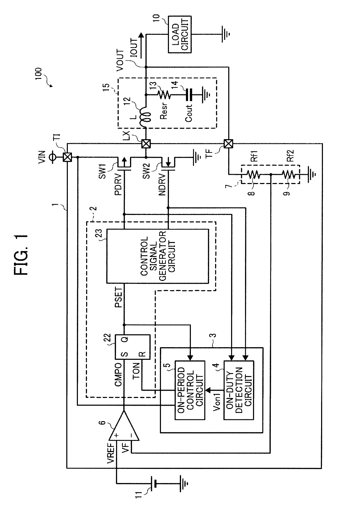
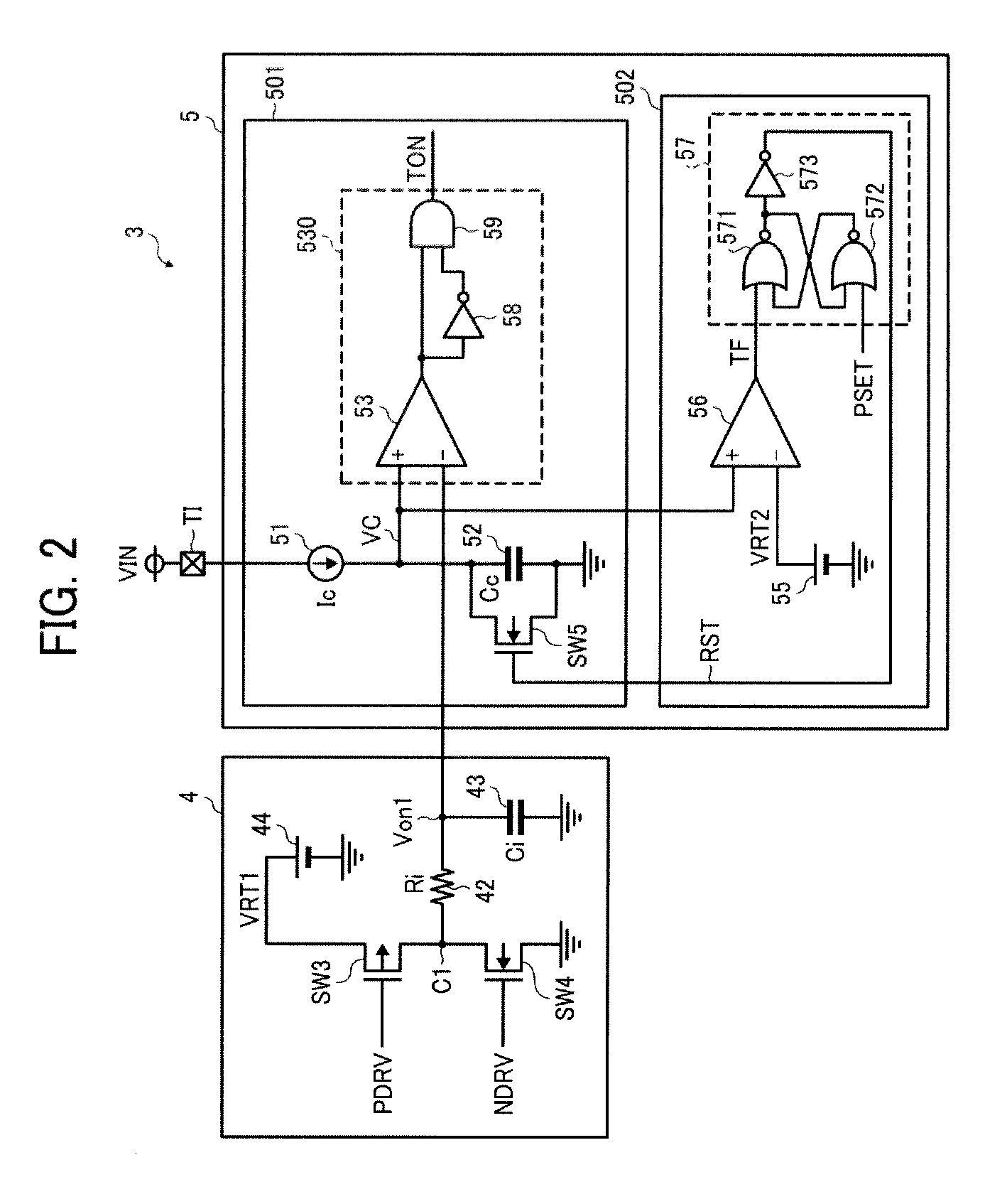
[0044]FIG. 1 is a circuit diagram illustrating the configuration of a switching regulator 1 according to a first embodiment. FIG. 2 is a circuit diagram illustrating the configuration of a switching-time control circuit 3 of the switching regulator 1. FIG. 3 is a timing chart illustrating operation in the switching regulator 1 shown in FIG. 1.

[0045]The switching regulator 1 of the present disclosure is installed in, for example, electronic devices 100 such as personal computers, and is used for supplying direct current to a load circuit 10 (e.g., a CPU, etc.).

[0046]In FIG. 1, the switching regulator 1 includes a switching-element control circuit 2, the switching-time control circuit 3, a comparator 6, switching elements SW1 and SW2, a dividing circuit 7 including a dividing resistor 8 having resistance Rf1 and a dividing resistor 9 having resistance Rf2, an input terminal TI to which an input voltage VIN is input, an output terminal LX, and a feedback terminal TF. The switching regu...

second embodiment

[0117]FIG. 4 is a circuit diagram illustrating a configuration of a switching-time control circuit 3A according to a second embodiment. In the second embodiment, the switching-time control circuit 3A includes an ON-duty detection circuit 4A instead of the ON-duty detection circuit 4 in the switching-time control circuit 3 in the first embodiment.

[0118]The ON-duty detection circuit 4A includes a reference voltage source 44, a switching element SW3, a switching element SW4, a charge reference current source 47, a discharge-reference current source 48, and a capacitor 43. The reference voltage 44 generates a reference voltage VRT. The switching element SW3 has a one terminal connected to the reference voltage source 44 and is turned on and off in conjunction with the switching element SW1. The charge-reference current source 47 is connected to the other terminal of the switching element SW3 and outputs a charge reference current Icp. The switching element SW4 has a one terminal connect...

third embodiment

[0128]FIG. 5 is a circuit diagram illustrating a switching-time control circuit 3B according to a third embodiment. The switching-time control circuit 3B in the present embodiment includes an ON-duty detection circuit 4B instead of the ON-duty detection circuit 4 in the switching-time control circuit 3 according to the first embodiment.

[0129]Herein, the ON-duty detection circuit 4B further includes a dividing circuit 49 to divide the reference voltage VRT for output to the switching element SW3. More specifically, the dividing circuit 49, serving as a first dividing circuit, is connected between the reference voltage source 44 and the third switching element SW3, to divide the second reference voltage VRT for output to the third switching element SW3.

[0130]The dividing circuit 49 is constituted by resistors 491 and 492 connected in serial between the reference voltage source 44 and the ground.

[0131]Accordingly, in FIG. 5, the capacitor 43 is charged to the reference voltage VRT afte...


PUM


Abstract

A switching regulator switch between an input terminal and an output terminal; a second switch between the output terminal and ground; a switching-time control circuit to generate a first signal when a first period corresponding to a ratio of ON-period of the first switch to a sum of those of the switches has elapsed from a reset-release timing and a reset signal when a second period longer than the first period has elapsed from the rest-release timing; a comparator to generate a second signal when a feedback voltage is smaller than a reference voltage; and a switch control circuit to control the switches so that the first switch is turned off and the second switch is turned on in response to the first signal, and the second switch is turned off and the first switch is fumed on in response to the second signal.

Description

CROSS-REFERENCE TO RELATED APPLICATIONS[0001]This patent application is based on and claims priority pursuant to 35 U.S.C. §119 to Japanese Patent Application Nos. 2011-221556, filed on Oct. 6, 2011 and 2012-201869 filed on Sep. 13, 2012 in the Japan Patent Office, the entire disclosures of which are hereby incorporated by reference herein.BACKGROUND[0002]1. Technical Field[0003]The present disclosure relates to a switching regulator to supply a highly precise voltage to a load circuit (e.g., a CPU, etc.), and an electronic device employing the switching regulator.[0004]2. Description of the Related Art[0005]At present, varieties of different applications are typically installed in mobile phones. The applications themselves tend to consume battery power at very high rates, and as a result, a power supply circuit whose external components are compact while at the same time able to handle large currents and low output voltages is needed. In addition, improvements in discharge characte...

Claims


Application Information

Patent Timeline
IPC IPC(8): G05F1/10
CPCH02M2001/0003H02M3/158H02M1/0003G05F1/10G05F1/565G05F1/575
Inventor NODA, IPPEI
Owner NISSHINBO MICRO DEVICES INC
Why Eureka
Try Eureka