micrometer

a micrometer and display technology, applied in the field of digital display micrometers, can solve problems such as painting the usability of micrometers, and achieve the effects of high accuracy measurements, and avoiding thermal expansion errors

Active Publication Date: 2013-04-18
MITUTOYO CORP
View PDF7 Cites 16 Cited by
  • Summary
  • Abstract
  • Description
  • Claims
  • Application Information

AI Technical Summary

Benefits of technology

[0025]Thus, when the finger rest is provided by a material with low heat conductivity, the heat is not transferred from the hand of the user to the body and, consequently, thermal expansion of the body can be avoided. Accordingly, the error due to the thermal expansion of the body can be avoided and the object can be highly accurately measured.

Problems solved by technology

However, when the micrometer is operated only with a left hand, a user cannot operate the operation button since the operation button is not provided on the backside, thereby impairing the usability of the micrometer.

Method used


Image

  • micrometer
  • micrometer
  • micrometer

Examples


Embodiment Construction

)

[0034]An exemplary embodiment of the invention will be described below with reference to the attached drawings.

[0035]Arrangement of Micrometer

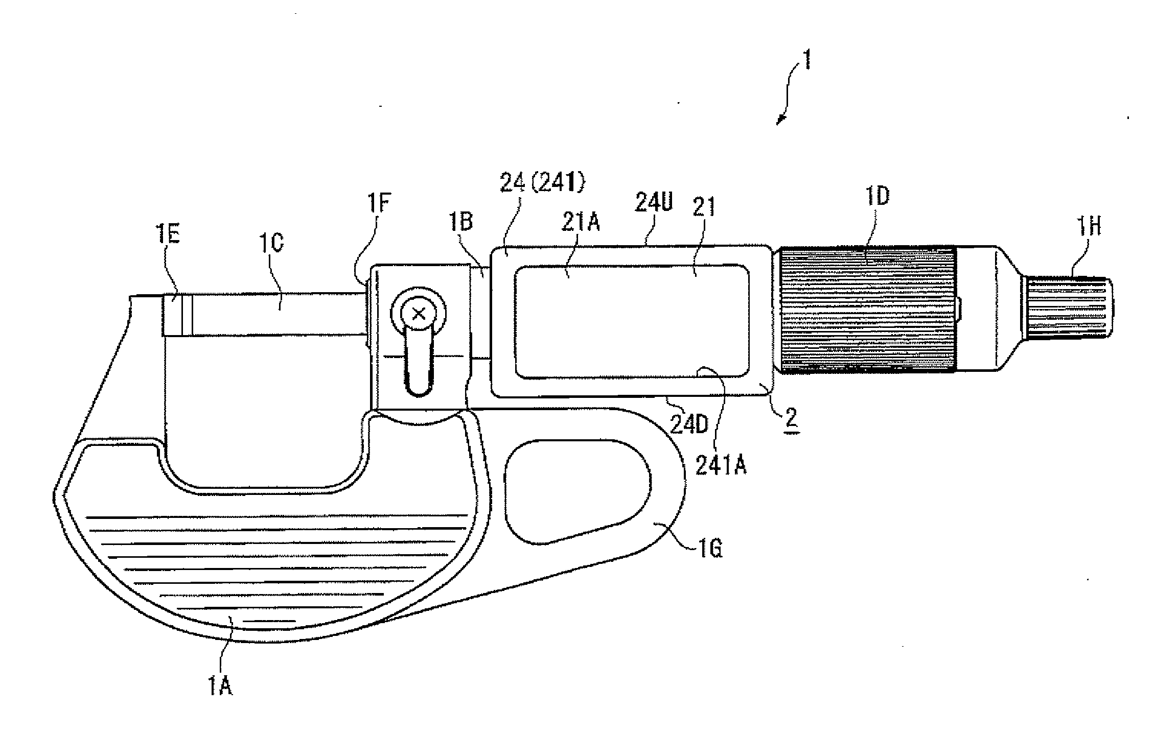
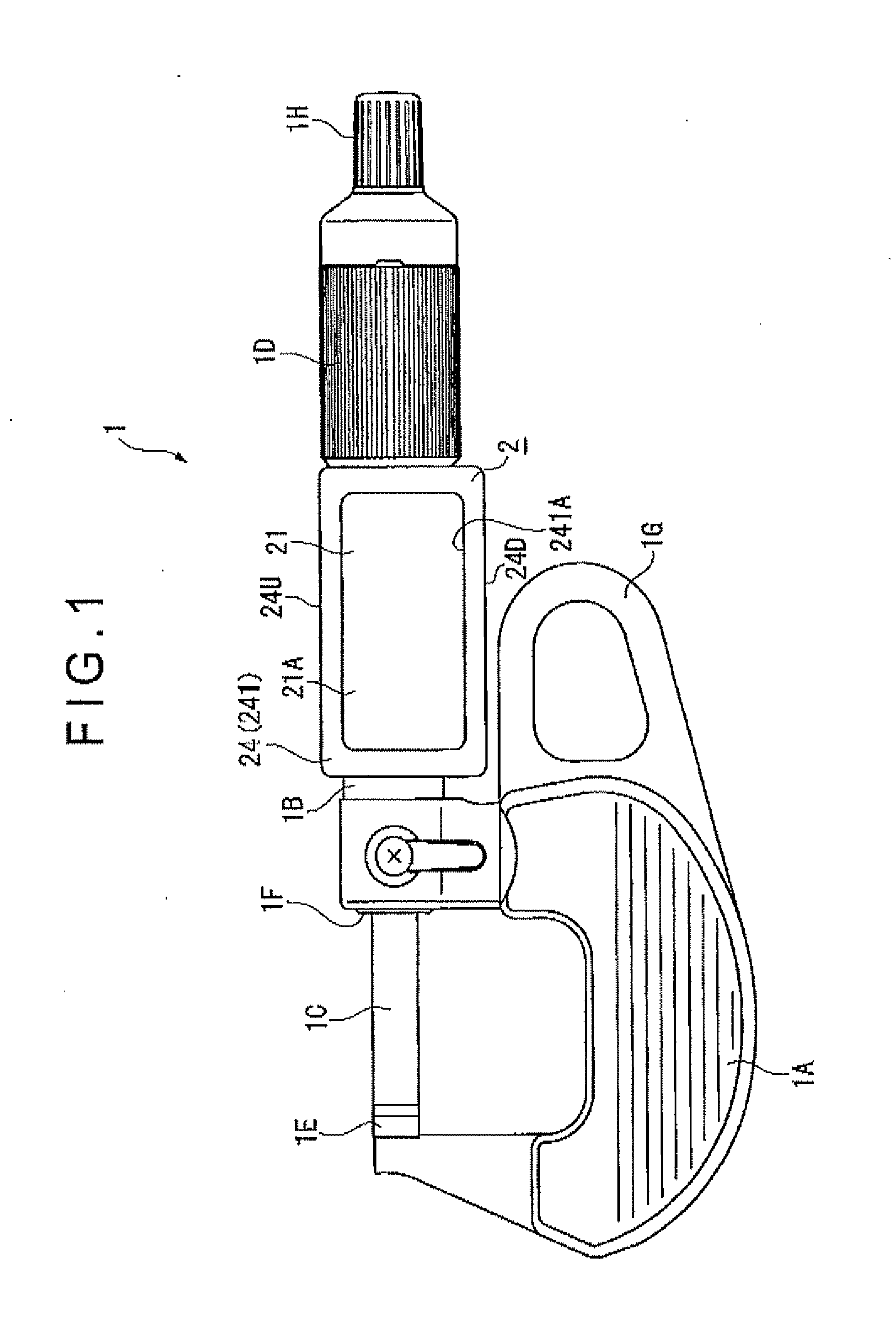
[0036]FIG. 1 is a front elevation showing an arrangement of a micrometer 1 according to the exemplary embodiment of the invention.

[0037]It should be noted that images displayed on a digital display 2 are not shown in FIG. 1 for the convenience of description.

[0038]As shown in FIG. 1, the micrometer 1 includes a body 1A, a fixed sleeve 1B, a spindle 1C, a thimble 1D, a digital display 2 (display device), an encoder 3 (displacement detector) (see FIG. 4) and a control device 4 (see FIG. 4).

[0039]Since the components 1A to 1D are well known components used in typical micrometers, the description of the components 1A to 1D will be simplified below.

[0040]As shown in FIG. 1, the body 1A is a substantially U-shaped member.

[0041]An anvil 1E is rigidly attached to a first end of the body 1A. A bearing cylinder 1F into which the spindle 1C is adapted t...


PUM


Abstract

A micrometer includes: a displacement detector that detects a displacement of a spindle; a display device that is rotatably attached to a fixed sleeve; and a control device that controls the display device. The display device includes: an image display section that displays an image including a measurement value based on the displacement detected by the displacement detector; a surface member that faces the image display section and has a touch surface; a position sensor that detects a position pressed on the touch surface; and a support member that supports the image display section, the surface member and the position sensor while the touch surface is exposed to an outside, the support member being rotatably attached to the fixed sleeve.

Description

[0001]The entire disclosure of Japanese Patent Applications No. 2011-228997 filed Oct. 18, 2011 is expressly incorporated by reference herein.BACKGROUND OF THE INVENTION[0002]1. Field of the Invention[0003]The present invention relates to a digital display micrometer.[0004]2. Description of Related Art[0005]Some of known digital display micrometers are arranged so that measurement values displayed on digital displays are readable irrespective of orientations of the micrometers during a measurement (see, for instance, Literature 1: JP-A-2005-227080 (FIGS. 5 and 6)).[0006]The micrometer disclosed in the Literature 1 is provided with a rotary unit that is rotatable around an axis that is parallel to an axial direction of a spindle. The rotary unit is provided thereon with a digital display.[0007]Accordingly, irrespective of whether operating the micrometer only with a right hand (i.e. when a front side of the micrometer is visible) or operating the micrometer only with a left hand (i.e...

Claims


Application Information

Patent Timeline
Patent Type & Authority Applications(United States)
IPC IPC(8): G01B3/18
CPCG01B3/18
Inventor HAYASHIDA, SHUJI
Owner MITUTOYO CORP
Why Eureka
Try Eureka