

Container for transporting and/or storing radioactive materials
a technology for radioactive materials and containers, applied in the field of containers for transporting and/or storing radioactive materials, can solve the problems of deterioration of mechanical characteristics of materials used for manufacturing storage devices, difficult to evacuate the heat released by nuclear fuel assemblies, and weakened integration of fuel pencils which constitute the assemblies
Active Publication Date: 2013-04-18
TN INT (FR)
View PDF4 Cites 12 Cited by
- Summary
- Abstract
- Description
- Claims
- Application Information
AI Technical Summary
Benefits of technology
The technical effect of this patent is to provide a simple, low-cost and effective solution to problems related to excessive noise and vibration in industrial equipment. This solution helps to avoid the related disadvantages and improve the overall performance of the equipment.
Problems solved by technology
If this temperature is exceeded the integrity of the fuel pencils which constitute the assemblies could indeed be weakened due to the potential deterioration of the mechanical characteristics of the pencil claddings.
But the mechanical characteristics of the materials used for manufacturing the storage devices can deteriorate, depending on the temperature, in particular when these materials are aluminium or one of its alloys.
One of the disadvantages resulting from the use of substantial manufacturing tolerances lies in the need to increase appreciably the clearance habitually allowed to make it possible and easy to load a detachable storage device into the cavity of the packaging, as mentioned above.
The clearance maintained then leads to a thermal insulation effect which runs counter to the overall aim sought of thermal conduction between the storage device and the packaging, thereby making it difficult to evacuate the heat released by the nuclear fuel assemblies.
However, the moving structure proposed in the abovementioned document is relatively complex and costly.
In addition, when it is deployed this structure has thermal bridges the small span of which limits the ability of this structure to conduct heat.
Method used
View moreImage
Smart ImageViewing Examples

Examples
first embodiment
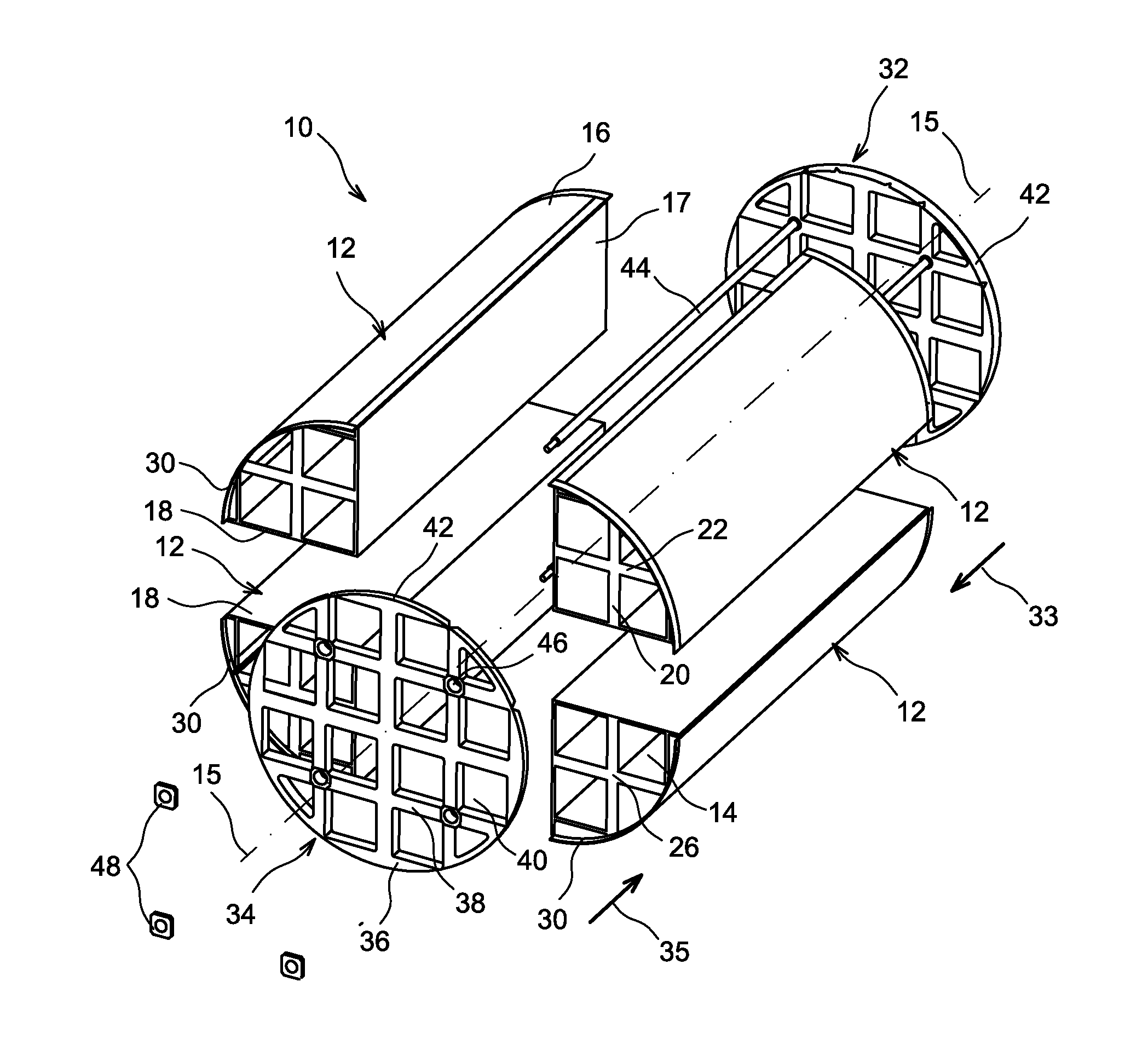
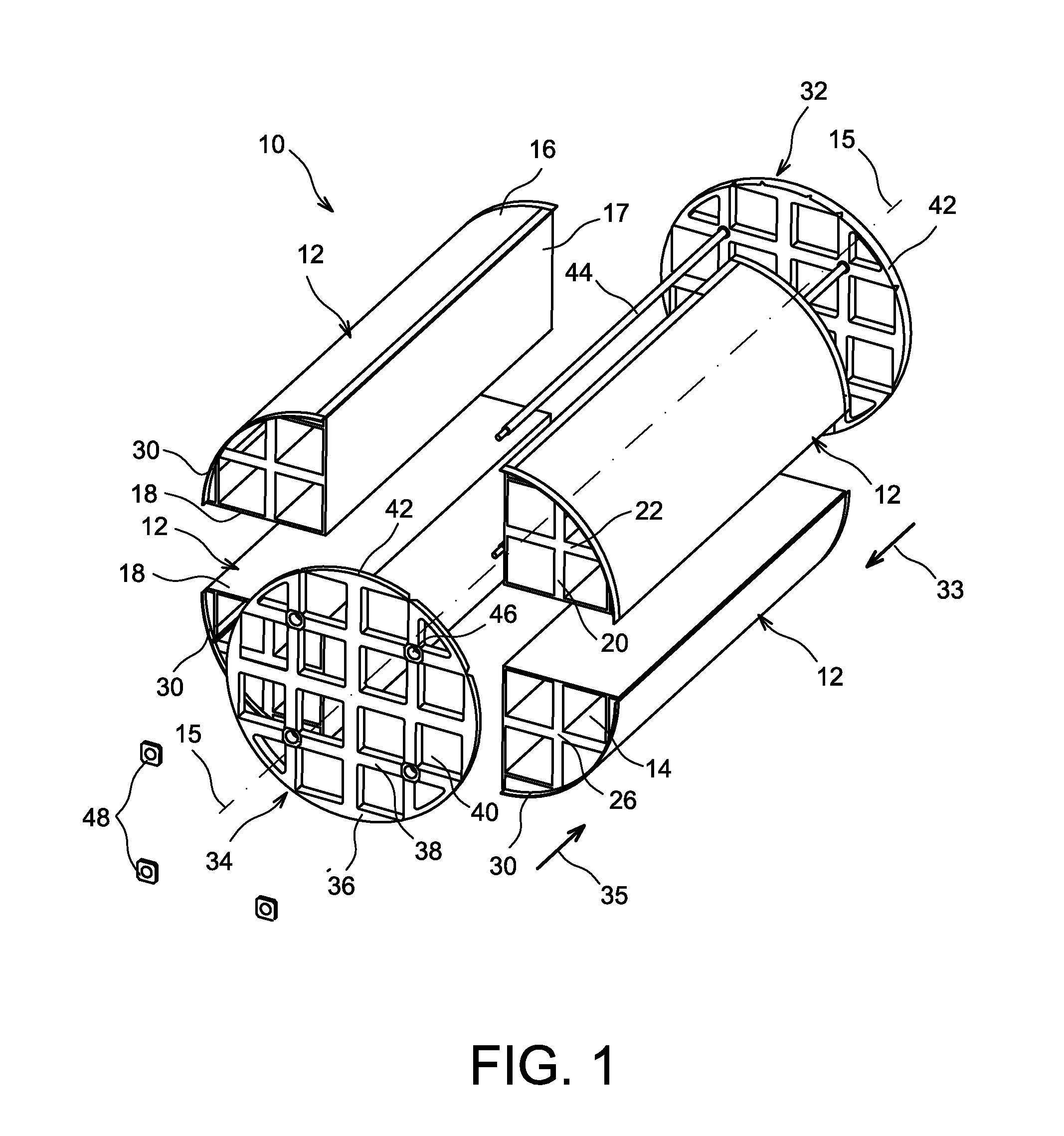
[0051]FIG. 1 is a schematic exploded perspective view of a storage device according to the invention;
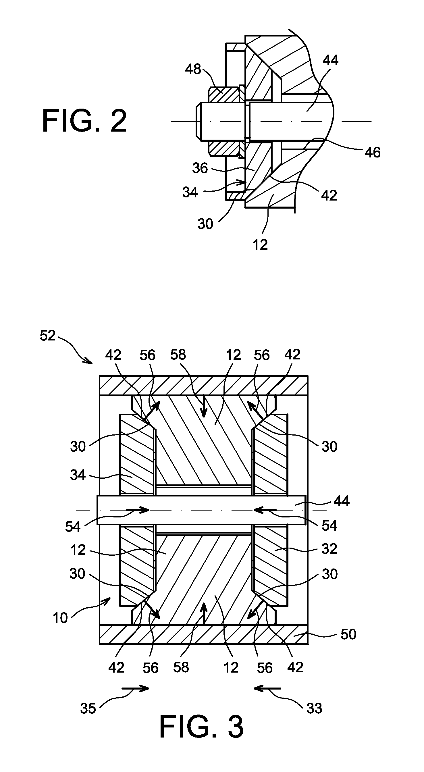
[0052]FIG. 2 is a partial diagrammatic view as an axial section of the storage device of FIG. 1;
[0053]FIG. 3 is a functional diagram of the storage device of FIG. 1;
second embodiment
[0054]FIG. 4 is a schematic view as an axial section of a storage device according to the invention, in a deployed position;
[0055]FIG. 5 is a diagrammatic view as an axial section of the storage device of FIG. 4, in a retracted position.
[0056]In all these figures, identical references designate identical or comparable elements.
Login to View More PUM
 Abstract
A removable storage device intended to be housed in a cavity of a form of packaging for transporting and / or storing radioactive materials, including several substructures movable relative to one another, positioned around a longitudinal axis, and defining multiple adjacent recesses for radioactive materials, together with means for deployment of the substructures including actuation means acting by shape collaboration on the substructures through a bearing surface having, in a section according to any plane passing through longitudinal axis, the shape of a segment inclined relative to this axis, such that displacement of actuation means in a first direction parallel to longitudinal axis causes a displacement of the substructures radially towards the exterior relative to longitudinal axis.
Description
TECHNICAL FIELD[0001]The present invention relates generally to the field of the transport and / or storage of radioactive materials, such as assemblies of irradiated nuclear fuel.[0002]However, the invention could also apply to the field of transport and / or storage of assemblies of fresh nuclear fuel, for example of the MOX type, without going beyond the scope of the invention.[0003]It could also find an application in the field of the transport and / or storage of other types of radioactive materials, namely and more specifically radioactive materials releasing substantial thermal power, such as vitrified waste, also called “glasses”, which are fission products.STATE OF THE PRIOR ART[0004]During the transport and / or storage of nuclear fuel assemblies, the latter are habitually housed in storage devices, also called storage “baskets” or “racks”. Such a device is generally cylindrical in shape with a roughly circular section, and has multiple adjacent recesses each one of which is able ...
Claims
Login to View More Application Information
Patent Timeline
 Patent Type & AuthorityApplications(United States)
IPC IPC(8): B65D85/00B65D25/00
CPCG21F5/012B65D85/70B65D25/00G21F5/10
InventorROGER, CHRISTOPHE
OwnerTN INT (FR)