Supercharge Your Innovation With Domain-Expert AI Agents!

Soft Skin Metal Seal and Technique of Manufacture

a metal seal and soft skin technology, applied in the field of soft skin metal seals and manufacturing techniques, can solve the problems of local hardness reduction of heat treatment at the sealing surface area, and achieve the effects of less cost, reduced hardness, and relatively simple varied strength seals

Inactive Publication Date: 2013-04-18
VETCO GRAY
View PDF8 Cites 6 Cited by
  • Summary
  • Abstract
  • Description
  • Claims
  • Application Information

AI Technical Summary

Benefits of technology

The patent describes a seal design that uses a soft material to seal with inner and outer wellhead members. This soft material is reinforced with wickers and a harder material to handle the mechanical loads. The resulting seal is stronger than traditional designs and can withstand damage and extreme pressure. The manufacturing process is simple and cost-effective.

Problems solved by technology

The heat treatment reduces the hardness locally at the sealing surface area.

Method used


Image

  • Soft Skin Metal Seal and Technique of Manufacture
  • Soft Skin Metal Seal and Technique of Manufacture
  • Soft Skin Metal Seal and Technique of Manufacture

Examples


Embodiment Construction

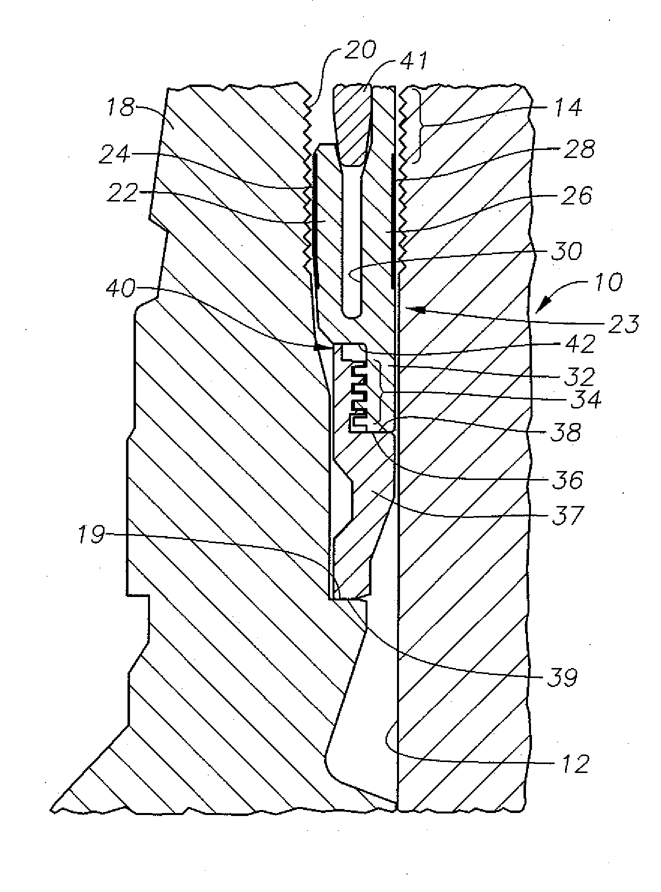
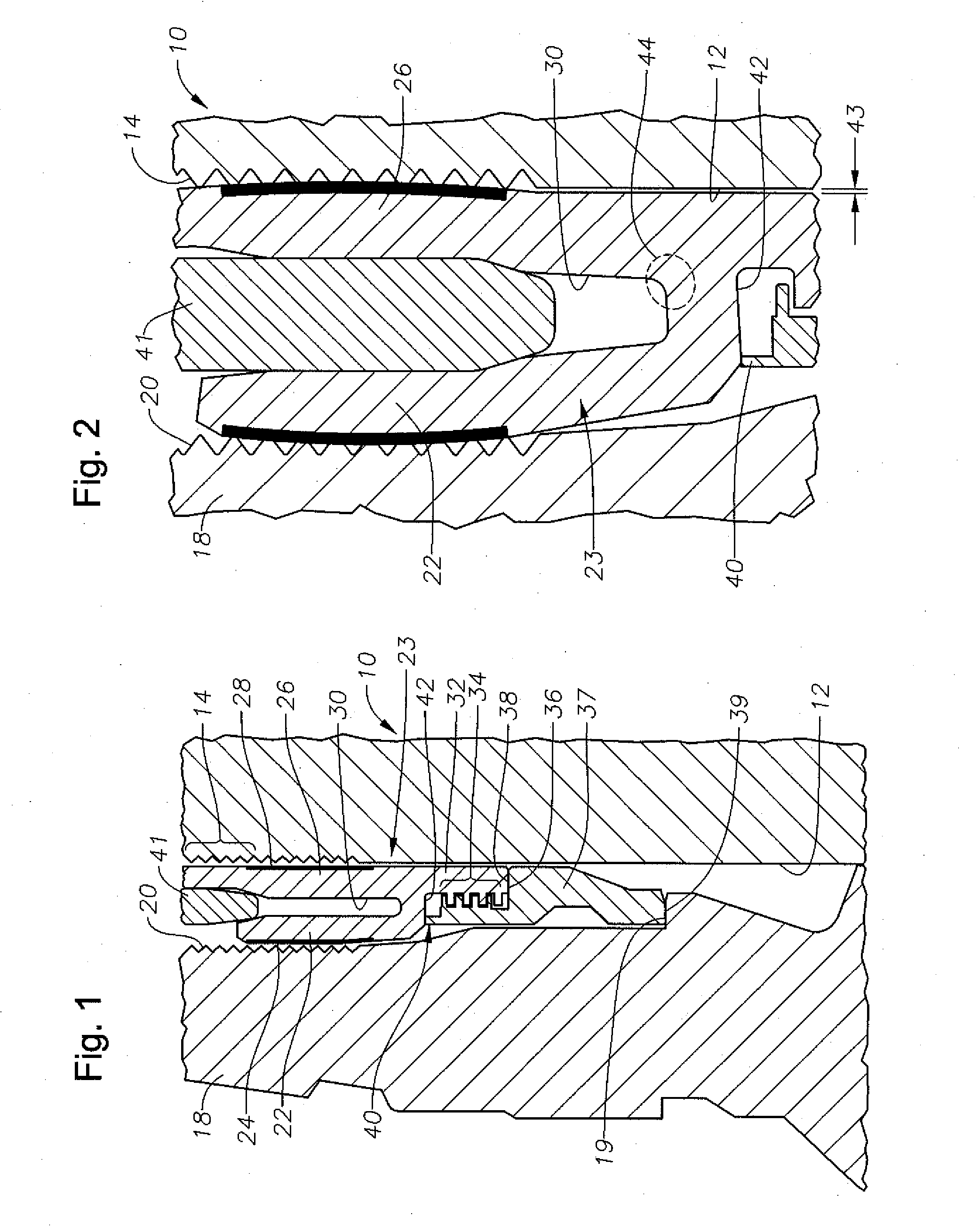
[0015]NON Referring to FIG. 1, a portion of a seal assembly is shown between an outer wellhead member, such as a wellhead housing 10 having a bore 12 with wickers 14 formed thereon and an inner wellhead member, such as a casing hanger 18 with wickers 20 formed on an exterior portion. Housing 10 is typically located at an upper end of a well and serves as the outer wellhead member 10. Alternately, wellhead housing 10 could be a tubing spool or a Christmas tree and casing hanger 18 could instead be a tubing hanger, plug, safety valve, or other device. The casing hanger 18 has an upward facing shoulder 19 for supporting a lower portion of the seal assembly. A metal-to-metal seal assembly has an inner seal leg 22 with an inner wall 24 sealing against the cylindrical wall of casing hanger 18. Seal ring 23 has an outer seal leg 26 with an outer wall surface 28 that seals against wellhead housing bore 12. The wall surfaces 24, 28 may be curved and smooth and may be softer than the material...


PUM

PropertyMeasurementUnit
Temperatureaaaaaaaaaa
Fractionaaaaaaaaaa

Abstract

A seal assembly between a wellhead housing having a bore and a casing hanger, has an inner seal leg for sealing against hanger and an outer seal leg for sealing against housing. An extension extends downward from outer seal leg and is connected to a nose ring having a downward facing shoulder that rests on the hanger shoulder to provide a reaction point for setting operations. A sealing surface on the seal legs is heat treated to obtain a lower localized yield strength to provide improved sealing while maintaining mechanical load capability.

Description

FIELD OF THE INVENTION[0001]This invention relates in general to wellhead assemblies and in particular to a localized heat treating process that selectively softens the outer skin surface of a metal seal for improved sealing when deformed.BACKGROUND OF THE INVENTION[0002]Seals are used between inner and outer wellhead tubular members to contain internal well pressure. The inner wellhead member may be a casing hanger located in a wellhead housing and that supports a string of casing extending into the well. A seal or packoff seals between the casing hanger and the wellhead housing. Alternatively, the inner wellhead member could be a tubing hanger that supports a string of tubing extending into the well for the flow of production fluid. The tubing hanger lands in an outer wellhead member, which may be a wellhead housing, a Christmas tree, or a tubing head. A packoff or seal seals between the tubing hanger and the outer wellhead member.[0003]A variety of seals located between the inner...

Claims


Application Information

Patent Timeline
IPC IPC(8): E21B33/03C21D9/40E21B33/035
CPCE21B33/035E21B33/03E21B33/04
Inventor GETTE, NICHOLAS P.DROZDOWSKI, STANLEY
Owner VETCO GRAY
Features
  • R&D
  • Intellectual Property
  • Life Sciences
  • Materials
  • Tech Scout
  • Unparalleled Data Quality
  • Higher Quality Content
  • 60% Fewer Hallucinations
Learn More