Apparatus and method for indoor positioning

a technology of indoor positioning and apparatus, applied in the field of indoor positioning technology, can solve the problems of inability to use the gps system, inability to synchronize the time between pseudo satellites, and use of expensive high-precision cesium clocks for time synchronization, etc., and achieve the effect of accurate indoor positioning and low cos

Inactive Publication Date: 2013-04-18
ELECTRONICS & TELECOMM RES INST
View PDF0 Cites 4 Cited by
  • Summary
  • Abstract
  • Description
  • Claims
  • Application Information

AI Technical Summary

Benefits of technology

[0010]An aspect of the present invention provides an apparatus and method for accurate indoor positioning at a low cost.

Problems solved by technology

However, since a GPS signal may not be received indoors or in a shadow area in which tall buildings are concentrated, the GPS system may be unusable.
Accordingly, an expensive high-precision cesium clock may be used for time synchronization between GPS satellites.
However, since a cheap clock, for example, a temperature compensated crystal oscillator (TCXO) may be used for a pseudo satellite, time may not be synchronized among pseudo satellites.
However, since a separate reference station is to be installed, in addition to a pseudo satellite, and a separate wireless channel is to be used for transmitting correction information generated by the reference station, a system may be complex and installation and operation costs may increase.
Similarly, when the technology is used to commercialize a pseudo satellite, a system may be complex and installation and operation costs may increase.

Method used


Image

  • Apparatus and method for indoor positioning
  • Apparatus and method for indoor positioning
  • Apparatus and method for indoor positioning

Examples


Embodiment Construction

[0035]Reference will now be made in detail to exemplary embodiments of the present invention, examples of which are illustrated in the accompanying drawings, wherein like reference numerals refer to the like elements throughout. Exemplary embodiments are described below to explain the present invention by referring to the figures.

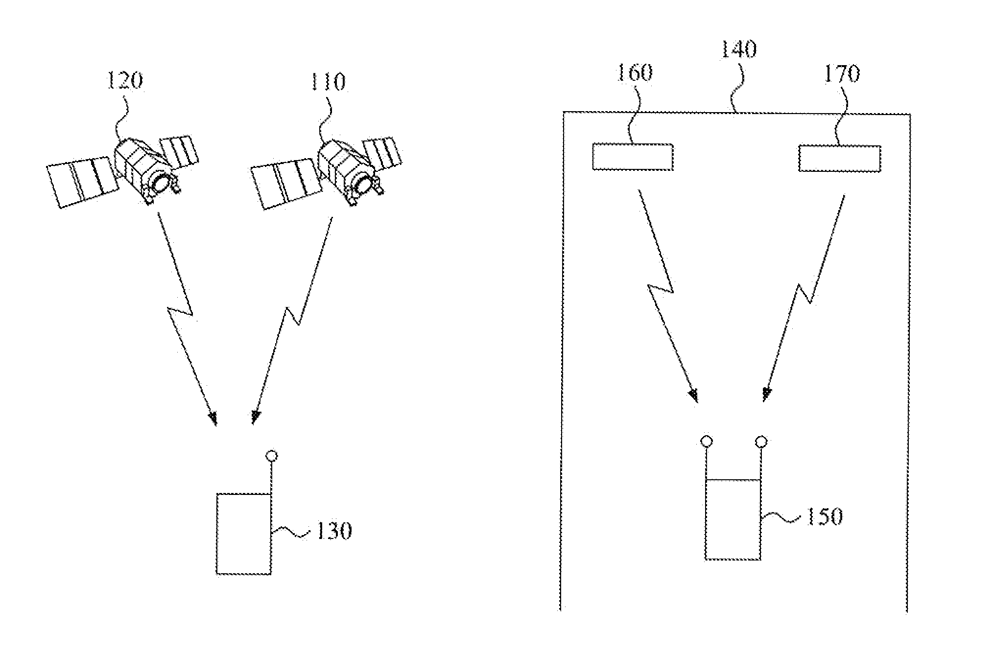
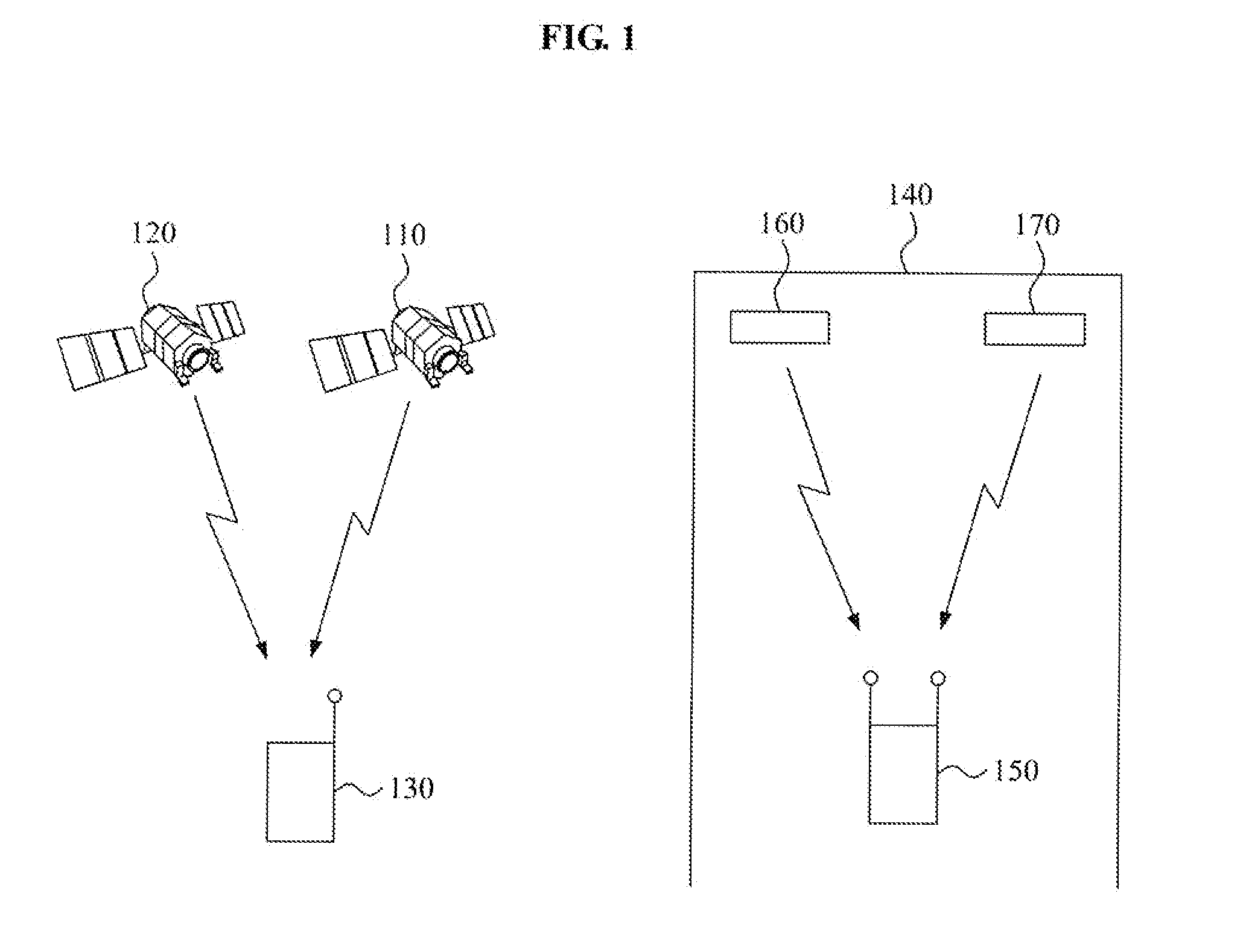
[0036]FIG. 1 is a diagram illustrating an indoor positioning system according to an exemplary embodiment of the present invention.

[0037]In a conventional positioning system, an outdoor terminal 130 may receive positioning signals from a satellite 110 and a satellite 120. The positioning signals may be synchronized with each other, and each of the positioning signals may include positional information of a corresponding satellite. The outdoor terminal 130 may estimate a distance from the satellite 110 to the outdoor terminal 130 and a distance from the satellite 120 to the outdoor terminal 130, based on the respective received positioning signals.

[0038]When ...


PUM


Abstract

Provided is a technique for estimating an indoor position, by which a terminal may receive a positioning signal from a pseudo satellite, using a plurality of receiving antennas, determine a position of the pseudo satellite based on positional information included in the received positioning signal, estimate a direction of the pseudo satellite based on a phase difference of the positioning signal at each of the plurality of receiving antennas, and estimate a location of the terminal based on the positional information of the pseudo satellite and the estimated direction of the pseudo satellite.

Description

CROSS-REFERENCE TO RELATED APPLICATIONS[0001]This application claims the benefit of Korean Patent Application No. 10-2011-0102507, filed on Oct. 7, 2011, and Korean Patent Application No. 10-2012-0029305, filed on Mar. 22, 2012, in the Korean Intellectual Property Office, the disclosures of which are incorporated herein by reference.BACKGROUND[0002]1. Field of the Invention[0003]The present invention relates to an indoor positioning technology, and more particularly, to a technology for measuring an indoor position using a positioning signal transmitted from a pseudo satellite not synchronized according to time.[0004]2. Description of the Related Art[0005]Verifying a position of a user is attracting attention as an important technology. Among positioning technologies for verifying a position of a user, the only satellite navigation system currently commercialized is the Global Positioning System (GPS). The GPS system was developed by the U.S. Department of Defense, and has been used...

Claims


Application Information

Patent Timeline
Patent Type & Authority Applications(United States)
IPC IPC(8): G01S19/11
CPCG01S19/11G01S5/08G01S5/0226G01S19/48
Inventor JOO, IN ONELEE, SANG UK
Owner ELECTRONICS & TELECOMM RES INST
Why Eureka
Try Eureka