Interbody Cage for Spinal Fusion and Method of Implanting Interbody Cages into Spines

a technology of spinal fusion and interbody cage, which is applied in the field of spinal stabilization, repair and/or reconstruction methods and devices, can solve the problems of insufficient rigidity and interbody fusion, insufficient surface area for adequate stabilization of the spine, and traditional devices and methods for lumbar interbody fusion that do not use minimally invasive techniques

Active Publication Date: 2013-04-18
5K IP 1
View PDF3 Cites 52 Cited by
  • Summary
  • Abstract
  • Description
  • Claims
  • Application Information

AI Technical Summary

Benefits of technology

[0008]In one aspect of the invention, a spinal interbody fusion implant in accordance with the invention comprises a leading end, a trailing end, opposite sides, a top, and a bottom. The trailing end has an impact rod fitting that is configured and adapted to be connected to an impact rod during implantation of the implant. The implant also comprises one or more openings that are encircled by portions of the implant and that extend into the top of the implant and continue through to and out of the bottom of the implant. The top and bottom of the implant each have a load bearing footprint. Each of the load bearing footprints has a centroid that is closer to the leading end of the implant than to the trailing end of the implant. The opposite sides and the leading and trailing ends of the implant each have a maximum horizontal dimension. The horizontal dimensions of the sides of the implant are greater than the horizontal dimensions of the leading and trailing ends of the implant.

Problems solved by technology

Traditional devices and methods for lumbar interbody fusion often do not use minimally invasive techniques and often do not provide adequate surface area to adequately stabilize the spine.
Traditional TLIF and TPLIF methods utilizing lumbar interbody fusion implants and unilateral screws often utilize implants that have footprints (i.e., projected horizontal bearing surface area capable of bearing vertical compression loads) that are inadequate to properly stabilize an anterior spine.
Such implants often lead to subsidence, may provide insufficient rigidity and interbody fusion, and often require stripping of the muscles in and around the spine.

Method used


Image

  • Interbody Cage for Spinal Fusion and Method of Implanting Interbody Cages into Spines
  • Interbody Cage for Spinal Fusion and Method of Implanting Interbody Cages into Spines
  • Interbody Cage for Spinal Fusion and Method of Implanting Interbody Cages into Spines

Examples


Embodiment Construction

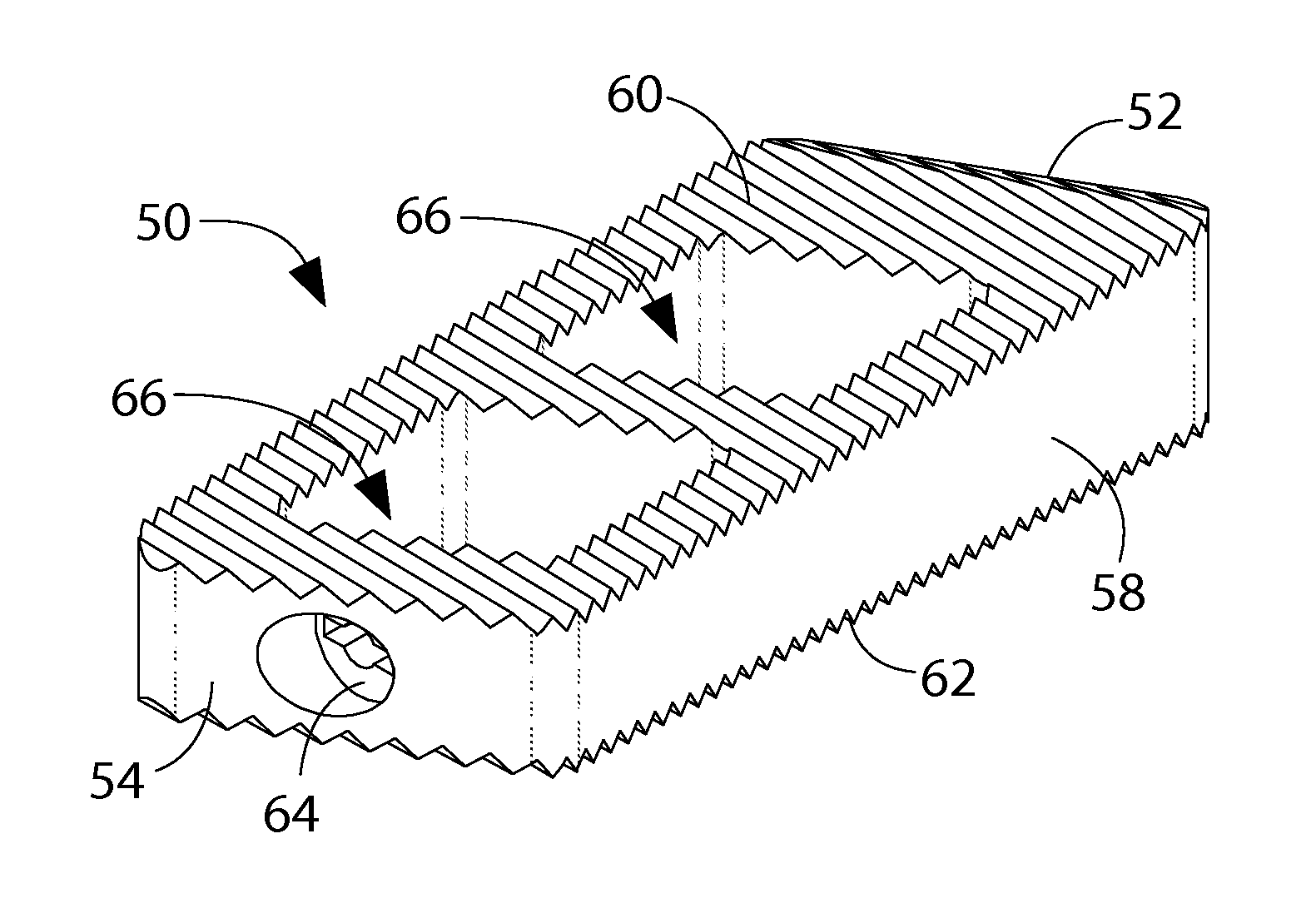
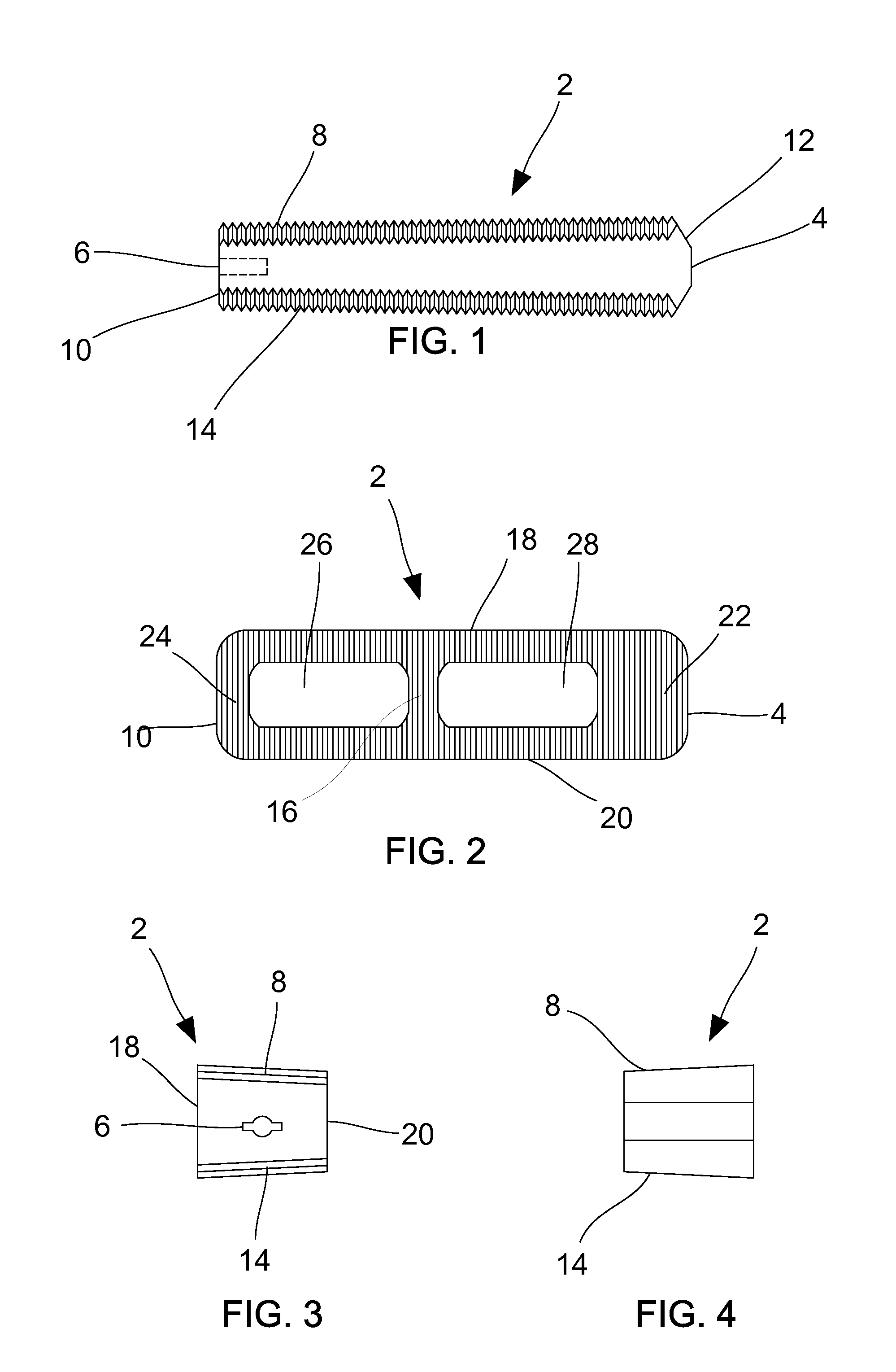
[0034]For purposes of describing the invention, the top of an implant herein means the portion of the implant that is generally superior in position relative to the remainder of the implant after the implant has been positioned between two vertebrae of a spine and when the spine is in a normal upright position. Similarly, the bottom of an implant means the portion of the implant that is generally inferior in position relative to the remainder of the implant when the implant has been positioned between the two vertebrae and the spine is in a generally upright position.

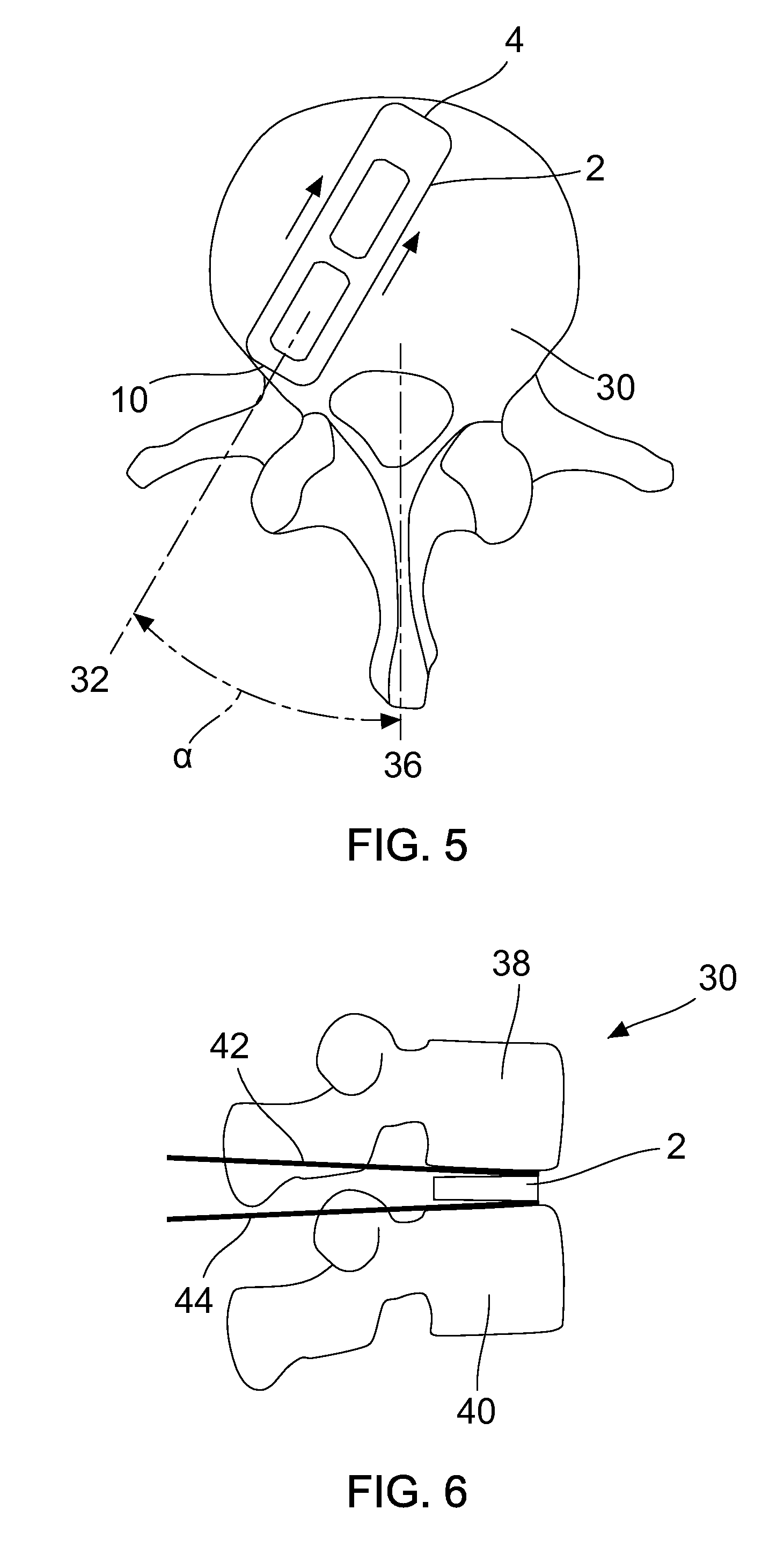
[0035]Some embodiments of spinal interbody fusion implants 2 in accordance with the invention are depicted in FIGS. 1-4 and 9-11. Each implant 2 may serve as an interbody spacer, disc replacement, or vertebral body replacement, that is positionable between an upper vertebral body 38 and a lower vertebral body 40 (See FIGS. 5-8). Referring to FIGS. 1, 3, and 4, each implant includes a top surface 8 and a bottom surface 1...


PUM


Abstract

A spinal interbody fusion implant has an impact rod fitting that is configured and adapted to be connected to an impact rod during implantation of the implant. The implant also comprises one or more openings that are encircled by portions of the implant and that extend into the top of the implant and continue through to and out of the bottom of the implant. The top and bottom of the implant each have a load bearing footprint. Each of the load bearing footprints has a centroid that is closer to the leading end of the implant than to the trailing end of the implant. A method of implanting a spinal interbody fusion implant between two vertebrae of a spine comprises inserting the implant into a patient through a posterior incision and guiding the implant into a position between the two vertebrae using a pair of shims.

Description

CROSS-REFERENCE TO RELATED APPLICATIONS[0001]This patent application is a non-provisional of provisional patent application Ser. No. 61 / 473,126, which was filed on Apr. 7, 2011, and is currently pending.STATEMENT REGARDING FEDERALLY SPONSORED RESEARCH OR DEVELOPMENT[0002]Not Applicable.APPENDIX[0003]Not Applicable.BACKGROUND OF THE INVENTION[0004]1. Field of the Invention[0005]This invention pertains to methods and devices for spinal stabilization, repair, and / or reconstruction. More particularly, this invention pertains to devices and methods for minimally invasive or open techniques for interbody fusion, for example, of the lumbar spine. Embodiments of the invention are applicable to transforaminal lumbar interbody fusion (“TLIF”) and / or transforaminal posterior lumbar interbody fusion (“TPLIF”).[0006]2. General Background[0007]Traditional devices and methods for lumbar interbody fusion often do not use minimally invasive techniques and often do not provide adequate surface area t...

Claims


Application Information

Patent Timeline
Patent Type & Authority Applications(United States)
IPC IPC(8): A61F2/44
CPCA61F2/442A61F2310/00029A61F2002/2835A61F2002/30158A61F2310/00131A61F2/447A61F2/4611A61F2002/3008A61F2002/30092A61F2002/30148A61F2002/30772A61F2002/30785A61F2002/30904A61F2002/4475A61F2002/4622A61F2310/00017A61F2310/00023A61F2/30767A61F2230/0086A61F2002/30593A61F2/4455
Inventor KUBE, II, RICHARD A.
Owner 5K IP 1
Why Eureka
Try Eureka