Laterally expanding intervertebral fusion device

a fusion device and intervertebral technology, applied in the field of intervertebral spacers, can solve the problems of reducing post-surgical pain and recovery time of patients, and extremely difficult surgery, and achieve the effects of reducing external volume or cross-sectional area, convenient insertion into disc space, and novel and particularly advantageous characteristics

Inactive Publication Date: 2005-04-14
WARSAW ORTHOPEDIC INC
View PDF51 Cites 27 Cited by
  • Summary
  • Abstract
  • Description
  • Claims
  • Application Information

AI Technical Summary

Benefits of technology

[0007] In general, this invention provides an expandable spacer for implantation between adjacent vertebrae to treat spinal defects. The spacer can be formed of a shape member polymer (SMP) and molded into a pre-selected configuration. Fabrication of the spacer using a shape memory polymeric material imparts novel and particularly advantageous characteristics to the intervertebral spacer. In a preferred embodiment, the spacer fabricated from a SMP can be molded into a desired configuration. However, when the spacer body is heated above a deformation temperature (Td) which is usually equivalent to the glass transition temperature (Tg) of the polymeric material, the polymeric material becomes elastic. When heated to a temperature equal to or above Td, the spacer body can be deformed to a wide variety of configurations by applying pressure or forcing it into a mold. The spacer body can be “frozen” into the deformed configuration by cooling it below the Td while the body is maintained in the deformed configuration. Thereafter the deformed spacer body retains the deformed configuration until it is heated above Td. When the spacer body is reheated above Td, the SMP again becomes elastic; and in the absence of any applied pressure, the spacer body automatically reverts to its original molded configuration. This process can be repeated any number of times without detrimental effect on the SMP or the spacer itself.
[0008] In one form, the

Problems solved by technology

Regardless of the direction of approach, the surgery is extremely difficult, and several organs, vessels and nerve structures must be avoided.
However, the oblique approaches only a

Method used


Image

  • Laterally expanding intervertebral fusion device
  • Laterally expanding intervertebral fusion device
  • Laterally expanding intervertebral fusion device

Examples


Embodiment Construction

[0025] For the purposes of promoting an understanding of the principles of the invention, reference will now be made to the embodiments illustrated herein and specific language will be used to describe the same. It will nevertheless be understood that no limitation of the scope of the invention is thereby intended. Any alterations and further modifications in the described processes, systems or devices, and any further applications of the principles of the invention as described herein, are contemplated as would normally occur to one skilled in the art to which the invention relates.

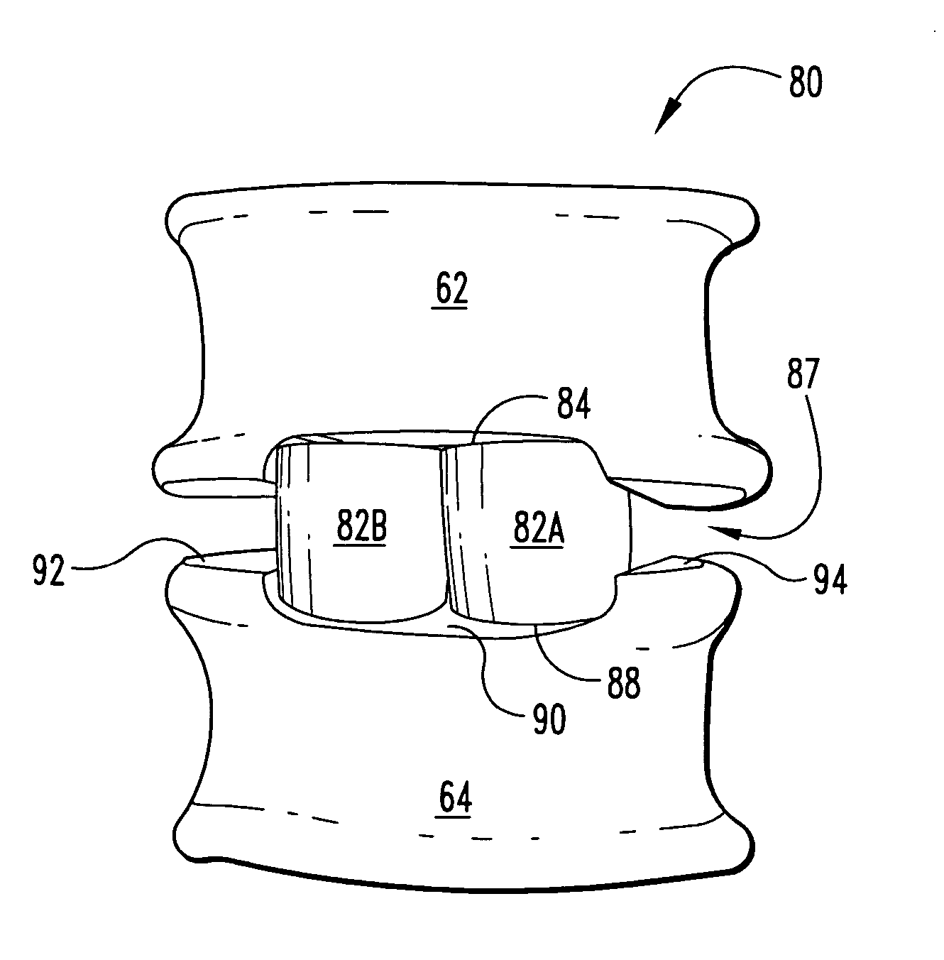
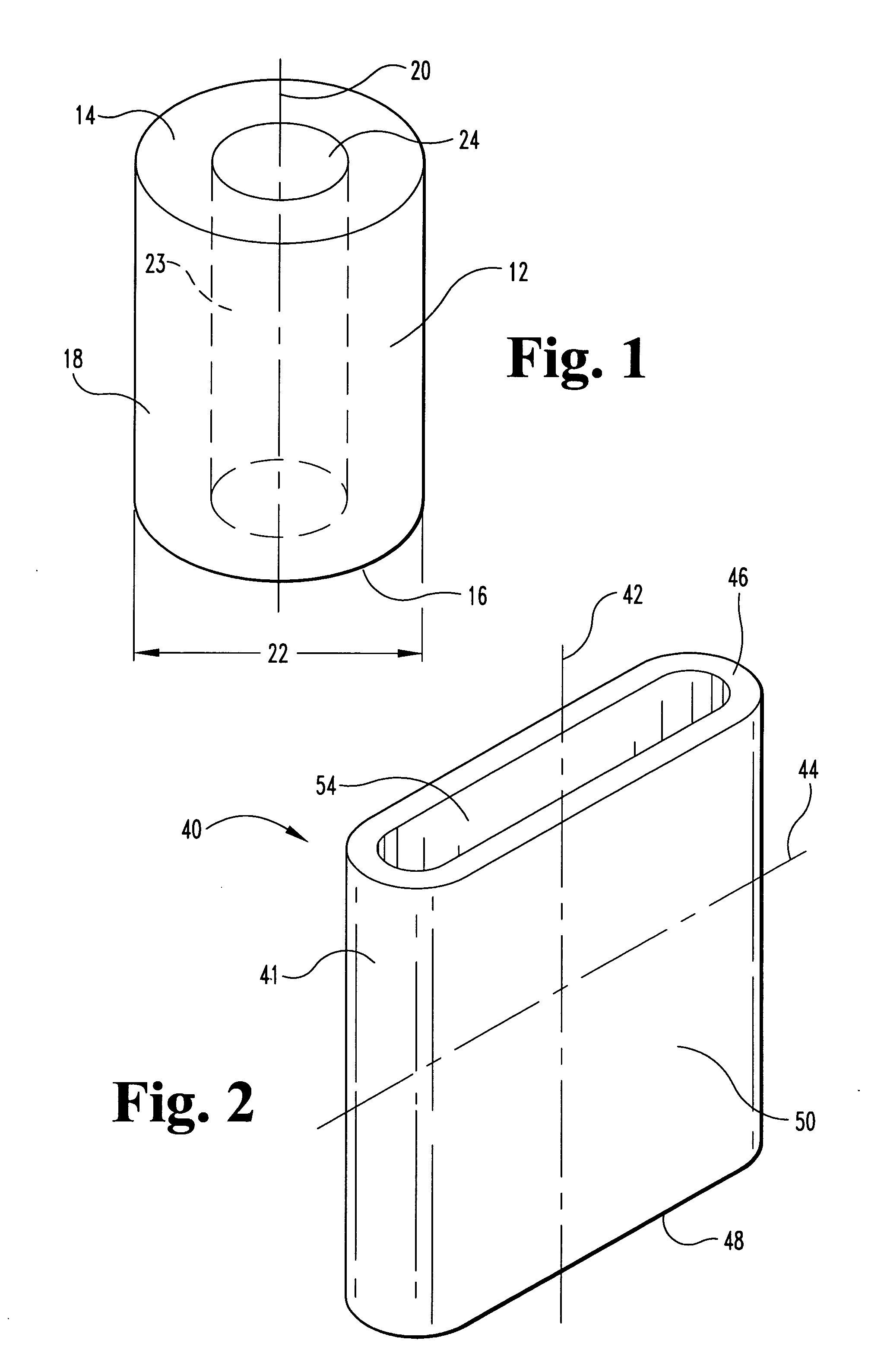
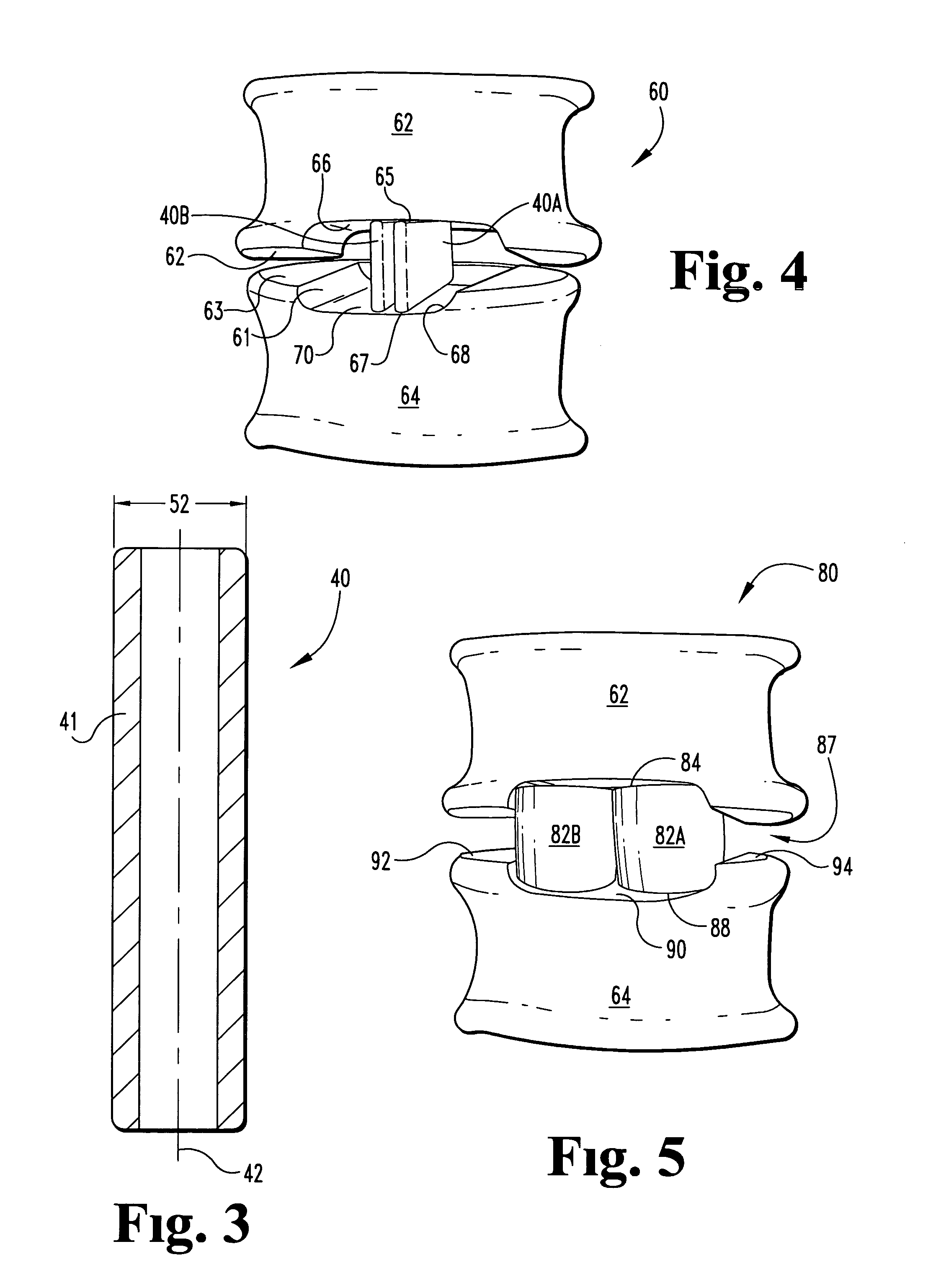
[0026] In general, this invention provides an expandable spacer for implantation between adjacent vertebrae to treat spinal defects. The spacer can be formed of a shape memory polymer (SMP) material and fabricated to a pre-selected, original configuration. The spacer can be heated to a deformation temperature (Td) and deformed into a first configuration, for example, a collapsed state exhibiting a reduc...


PUM

PropertyMeasurementUnit
Diameteraaaaaaaaaa
Diameteraaaaaaaaaa
Diameteraaaaaaaaaa

Abstract

This invention relates to intervertebral spacers for use in orthopedic treatment of spinal defects. The intervertebral space is formed of a shape memory polymer. The spacer can be fabricated into a desired configuration and then deformed into an alternative or deformed configuration. Cooling the deformed spacer effectively freezes the spacer into its deformed conformation. The deformed configuration can be selected to facilitate implantation of the spacer into a prepared disc space between adjacent vertebrae. During operation, the surgeon can heat the spacer to allow it to revert to its original configuration. The spacer in its original conformation is sized to restore and/or maintain the adjacent vertebrae in a desired conformation and disc space height.

Description

BACKGROUND OF THE INVENTION [0001] In general, this invention relates to intervertebral spacers and their use in orthopedic treatment. More specifically, the present invention is directed to intervertebral spacers composed of a shape memory polymeric material. The intervertebral spacers can be deformed and induced to recover their original configuration as desired to facilitate orthopedic treatment of spinal defects. [0002] Removal of damaged or diseased discs and implantation of intervertebral spacers into the disc space are known medical procedures used to restore disc space height, and to treat chronic back pain and other ailments. The spacers can be formed of a variety of materials—both resorbable and non-resorbable materials—including bone-derived material, metallic, ceramic, and polymeric materials. Typically, spacers are pre-formed into a general configuration that is easy to fabricate or, in selected examples, spacers are pre-formed to a generalized configuration that resemb...

Claims


Application Information

Patent Timeline
IPC IPC(8): A61F2/00A61L27/00A61F2/02A61F2/28A61F2/30A61F2/44A61F2/46
CPCA61F2/4455A61F2250/003A61F2002/2817A61F2002/2835A61F2002/30014A61F2002/30032A61F2002/30062A61F2002/30095A61F2002/30102A61F2002/30103A61F2002/30131A61F2002/30133A61F2002/30176A61F2002/30177A61F2002/30235A61F2002/30579A61F2002/30971A61F2002/4475A61F2002/448A61F2002/4635A61F2210/0004A61F2210/0023A61F2210/0042A61F2210/0047A61F2230/0013A61F2230/0015A61F2230/0054A61F2230/0056A61F2230/0069A61F2250/0018A61F2/4465A61F2002/30092A61F2002/30593
Inventor ESTES, BRADLEY T.DICKSON, ANDREW M.
Owner WARSAW ORTHOPEDIC INC
Why Eureka
Try Eureka