
Oil cooler formed by staggered dotting oil cooler pipes

A technology of oil cooler and pipe body, which is applied in the field of automobile radiator components, and can solve the problems of inability to realize the cooling effect of lubricating oil, unfavorable requirements for energy saving of automobiles, and high failure rate

Active Publication Date: 2021-04-20
NANNING ANHE MECHANICAL EQUIP CO LTD
View PDF31 Cites 0 Cited by
  • Summary
  • Abstract
  • Description
  • Claims
  • Application Information

AI Technical Summary

Problems solved by technology

However, the cooling area of ​​the above-mentioned pipe body is limited, and a better lubricating oil cooling effect cannot be achieved.
[0004] Therefore, the original water-cooled structure has gradually developed and transitioned to the air-cooled stacked oil cooler, but the air-cooled stacked structure has more parts and solder joints, the process is difficult, and the failure rate is high. Cost and The weight of a single piece is relatively high
At the same time, there are many parts, difficult process assembly, and large flow resistance and wind resistance, which is not conducive to the market's requirements for automobile energy saving
When assembling the oil cooler tube body into an oil cooler, due to the unreasonable structural design, the welding strength is insufficient, so that the working pressure that the oil cooling tube body can withstand during work is small, and the pressure intensity at the inlet and outlet ends of the oil cooling tube body is also low. Weak, can not meet the requirements of use

Method used


Image

  • Oil cooler formed by staggered dotting oil cooler pipes
  • Oil cooler formed by staggered dotting oil cooler pipes
  • Oil cooler formed by staggered dotting oil cooler pipes

Examples


Embodiment 1

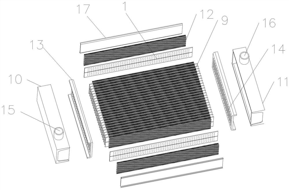
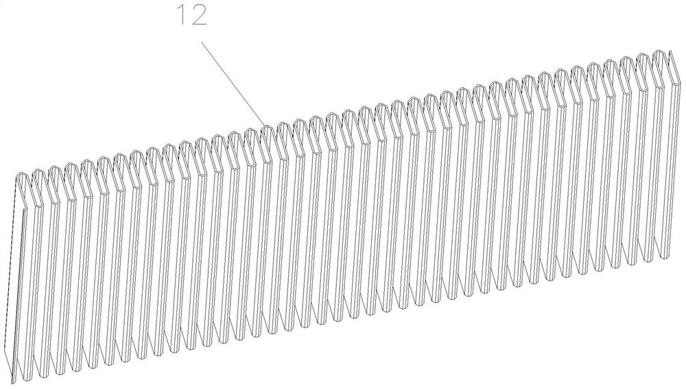
[0048] Such as Figure 1-4 As shown, the oil cooler made of misplaced oil cooler tubes in this embodiment includes a body, and the body includes a core 9 , an oil inlet chamber 10 and an oil outlet chamber 11 . The core 9 includes alternately arranged heat dissipation strips 12 and oil cooler tubes, the number of heat dissipation strips 12 is one more than that of the oil cooler tube, and the two outermost heat dissipation strips 12 on the core 9 are welded with shielding The plate 17 and the two ends of the core 9 are welded with a main piece 13, and the main piece 13 is provided with an oil hole 14 at a position corresponding to the oil cooler tube. An oil inlet chamber 10 and an oil outlet chamber 11 are respectively welded on the other side of the main piece 13 at both ends of the core 9 , the top of the oil inlet chamber 10 is provided with an oil inlet 15 , and the top of the oil outlet chamber 11 is provided with an oil outlet 16 . The heat dissipation strip 12 used in...

Embodiment 2

[0053] Such as Image 6 As shown, the difference between this embodiment and embodiment 2 is that the inner walls of both sides of the tube body 1 are provided with reinforcing pieces 5 , and the thickness of the reinforcing pieces 5 is equal to the wall thickness of the tube body 1 .

Embodiment 3

[0055] Such as Figure 7-8 As shown, the difference between this embodiment and Embodiment 1 is that the pipe body 1 is formed by bending a piece of sheet body, the bending part of the sheet body is provided with a first bending part 6, and the two free ends of the sheet body A second bent portion 7 and a third bent portion 8 are respectively provided. The first bending part 6 is formed by folding three layers of a sheet body, and the second bending part 7 and the third bending part 8 are formed by folding three layers of two free ends of the sheet body into the tube body 1 , and the heights of the second bending portion 7 and the third bending portion 8 are half of the height of the first bending portion 6, the first bending portion 6, the second bending portion 7, and the third bending portion 8 The thickness is the same after folding. The second bending portion 7 and the third bending portion 8 are closed by high frequency welding.

[0056] Working principle: The working...


PUM


Abstract

The invention discloses an oil cooler formed by staggered dotting oil cooler pipes. The oil cooler comprises a body, and the body comprises a core, an oil inlet chamber and an oil outlet chamber. The core comprises heat dissipation belts and the oil cooler pipes, the heat dissipation belts and the oil cooler pipes are arranged alternately, main pieces are welded to the two ends of the core, and oil passing holes are formed in the positions, corresponding to the oil cooler pipes, of the main pieces. The oil inlet chamber and the oil outlet chamber are welded to the main pieces of the core correspondingly, a groove is formed in a pipe body of each oil cooler pipe, and protection plates are welded to the two heat dissipation belts on the outer layer correspondingly. The oil cooler is small in weight, high in strength, capable of bearing large working pressure, high in assembling speed, convenient and fast to install, high in sealing performance and small in flow resistance and wind resistance. The oil cooler pipe is high in overall strength and good in stress dispersion, deformation, leakage and the like are not likely to occur in the using process, and the heat exchange efficiency, the sealing quality and the stability of the oil cooler are guaranteed. The oil cooler and the accessories used by the oil cooler have wide popularization and application value, and the market competitiveness of enterprises is improved.

Description

technical field [0001] The invention relates to the technical field of automobile radiator components, in particular to an oil cooler made of misplaced dotted oil cooler tubes. Background technique [0002] When the car is running, the temperature of the lubricating oil contained in the gearbox will continue to rise due to the transmission of power. If the temperature of the lubricating oil is too high, it may cause the lubricating oil to boil and lose its lubricating effect, thus making the gears easy to wear. How to ensure The lubricating oil temperature in the gearbox will not be too high, which becomes a very important issue. In the existing structural configuration of automobiles, oil cooler tubes are provided to cool lubricating oil and ensure that the oil temperature is within the normal working range. [0003] The automobile oil cooler in the prior art includes an oil cooler tube body, the oil cooler tube body has inner and outer double-layer tube walls, the tube en...

Claims


Application Information

Patent Timeline
Patent Type & Authority Applications(China)
IPC IPC(8): F16H57/04
CPCY02T10/12
Inventor 沈平黄乃玉韦佳梁立兴黄寿来黄新咏杨元豪
Owner NANNING ANHE MECHANICAL EQUIP CO LTD
Learn More