
Steel structure including pre-stressing brackets for improving load-carrying capacity and serviceability

a technology of steel structure and prestressing bracket, which is applied in the direction of girders, bridges, joists, etc., can solve the problems of inability to apply to the bridge for a long span, the lowering of the bearing capacity, and the inability to continuously cover the cover plate onto the steel girder, etc., to improve the load-bearing capacity, increase the prestressing effect, and increase the moment of inertia of section

Active Publication Date: 2013-04-25
YOOHO DEV & CONSTR +1
View PDF1 Cites 5 Cited by
  • Summary
  • Abstract
  • Description
  • Claims
  • Application Information

AI Technical Summary

Benefits of technology

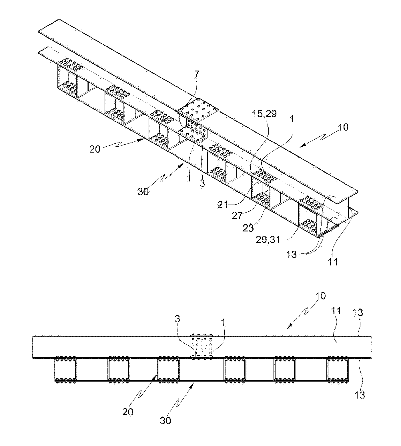
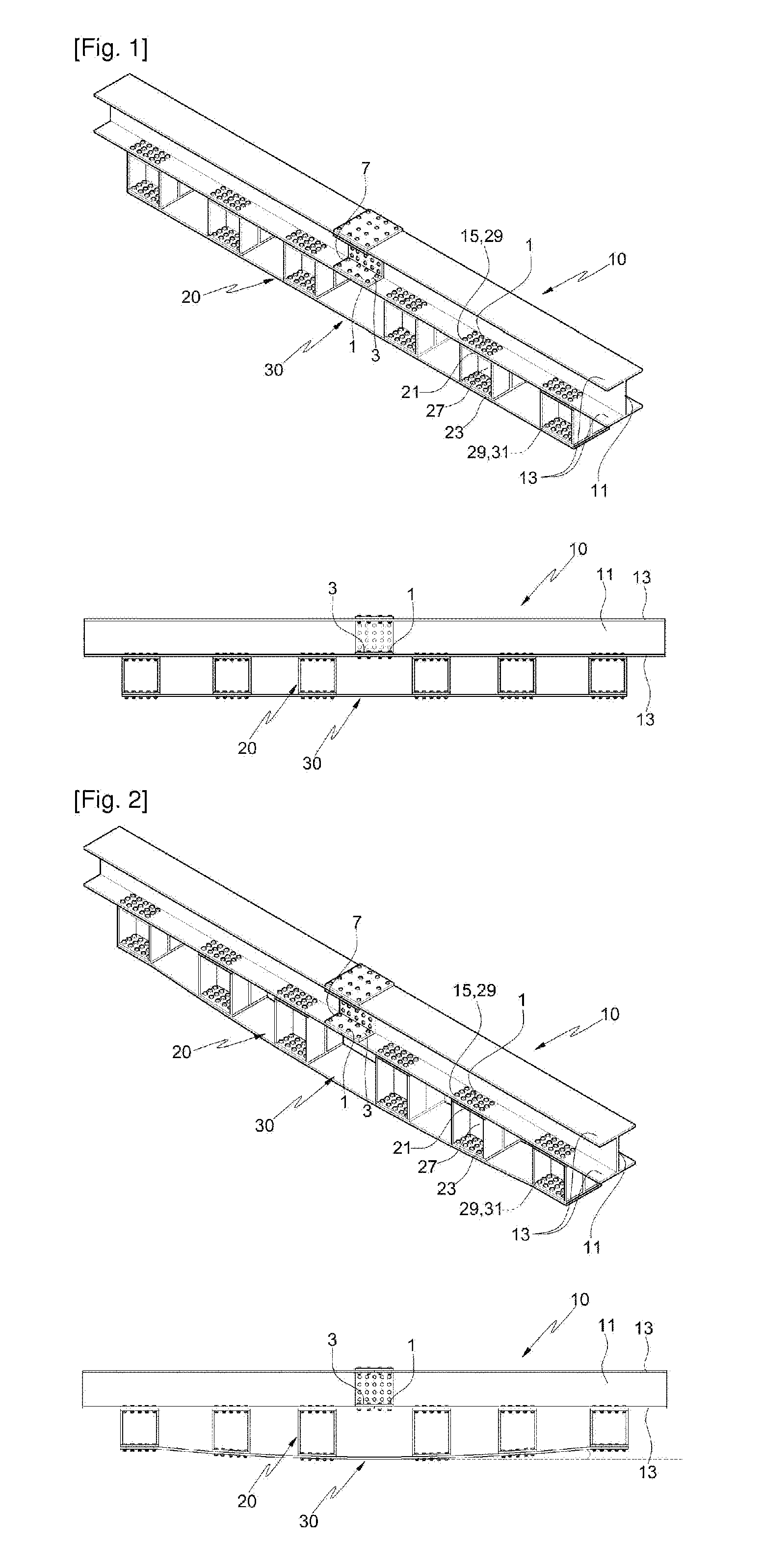
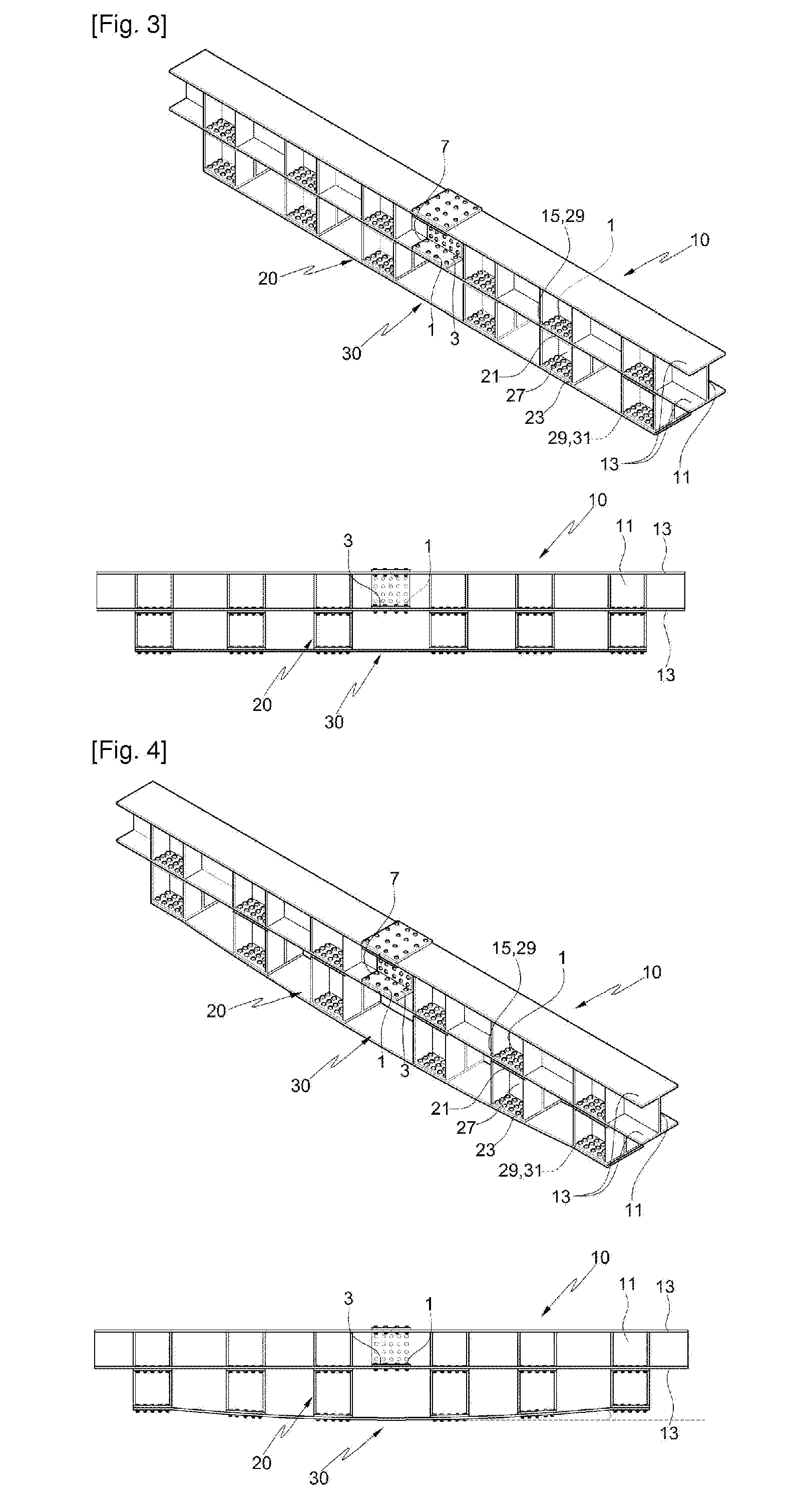
The present invention is about a steel structure that improves its load-bearing capacity and performance. The invention uses connecting brackets that are spaced apart from each other between the steel girder and the cover plate. This prevents the installation of the cover plate from being restricted by the connection points between neighboring steel channels, which allows for continuous introduction of prestressing ranges to increase the effect. The steel girder and the cover plate are also spaced apart, which increases the moment of inertia of the section and optimizes the efficiency of the section to create a long-span bridge. The connecting brackets gradually increase in height from both ends of the cover plate to the center, which strengthens the stiffness of the section and offsets the stress created by the weight of the steel structure, resulting in economical effects.

Problems solved by technology

Because of the connection portion where the high tension bolts are fastened to connect the flange and the steel plate, at this time, it is hard to continuously cover the cover plates onto the steel girders.
Furthermore, if the cover plate is connected directly to the steel girder in the conventional practice, the stiffness of the section caused by the moment of inertia of section is limited to the height of the steel girder, which causes the load-bearing capacity to be undesirably lowered, thereby making it impossible to be applicable to the bridge for long span.

Method used


Image

  • Steel structure including pre-stressing brackets for improving load-carrying capacity and serviceability
  • Steel structure including pre-stressing brackets for improving load-carrying capacity and serviceability
  • Steel structure including pre-stressing brackets for improving load-carrying capacity and serviceability

Examples


Embodiment Construction

[0028]Hereinafter, an explanation on A steel structure including pre-stressing brackets for improving load-carrying capacity and serviceability according to the present invention will be given with reference to the attached drawings.

[0029]According to the present invention, as shown in FIGS. 1a to 5b, a steel structure including pre-stressing brackets for improving load-carrying capacity and serviceability thereof, includes: a steel girder 10; a plurality of connecting brackets 20 connected to the bottom surface of the steel girder 10 and spaced apart from one another; and a cover plate 30 connected to the bottom surfaces of the connecting brackets 20.

[0030]In the steel structure including pre-stressing brackets for improving load-carrying capacity and serviceability thereof according to the present invention, the steel girder 10 is connected to piers or abutments of a bridge to form the upper structure of the bridge, and generally, H-beam or I-beam, which is used as the steel girde...


PUM


Abstract

A steel structure including pre-stressing brackets for improving load-carrying capacity and serviceability comprises: a steel girder; a plurality of connecting brackets connected to the bottom surface of the steel girder spaced and apart from one; and a cover plate connected to the bottom surfaces of the connecting brackets. Since the cover plate is installed regardless of the connecting portion of the steel girder, pre-stressing section can be consecutively formed therefore pre-stress effect is improved. Moreover, since the connecting brackets space the cover plate a constant distance from the steel girder, the moment of inertia is increased so the span of a bridge might be increased.

Description

BACKGROUND OF THE INVENTION[0001]The present invention relates to a steel structure including pre-stressing brackets for improving load-carrying capacity and serviceability thereof, and more particularly, to a steel structure including pre-stressing brackets for improving load-bearing capacity and use performance thereof wherein the connecting brackets are spaced apart from each other between a steel girder and a cover plate to prevent the installation of the cover plate from being limited by the connection portions of the neighboring steel girders, thereby allowing prestressing ranges to be continuously introduced to increase the prestressing effects, and the steel girder and the cover plate are spaced apart from each other by means of the formation of the connecting brackets, thereby increasing moment of inertia of section and optimizing section efficiency to provide a bridge for long span.[0002]Generally, a steel girder is formed of an H-beam or I-beam and is adapted to be connec...

Claims


Application Information

Patent Timeline
Patent Type & Authority Applications(United States)
IPC IPC(8): E04C5/16E04C5/08
CPCE01D2/00E04C3/04E04C2003/0417E04C2003/0434E01D2101/32E04C5/08E04C5/162E01D2/02E04C2003/0452
Inventor KIM, SANG HYOAHN, JIN HEEYOO, JUNG HOHAN, SEUNG SOOCHO, CHANG KEONCHOI, KYU TAE
Owner YOOHO DEV & CONSTR
Learn More