Robot cleaner and control method for the same

a robot cleaner and robot technology, applied in the field of robot cleaners, can solve the problems of increasing the possibility of auxiliary cleaning tools striking the wall, shifting the position of additional devices, and damaging additional devices,

a robot cleaner and robot technology, applied in the field of robot cleaners, can solve the problems of increasing the possibility of auxiliary cleaning tools striking the wall, shifting the position of additional devices, and damaging additional devices,

US20130098401A1Active Publication Date: 2013-04-25SAMSUNG ELECTRONICS CO LTD

Image

  • Robot cleaner and control method for the same
  • Robot cleaner and control method for the same
  • Robot cleaner and control method for the same

Examples


Embodiment Construction

[0064]Hereinafter, embodiments of the present disclosure will be described with reference to the accompanying drawings.

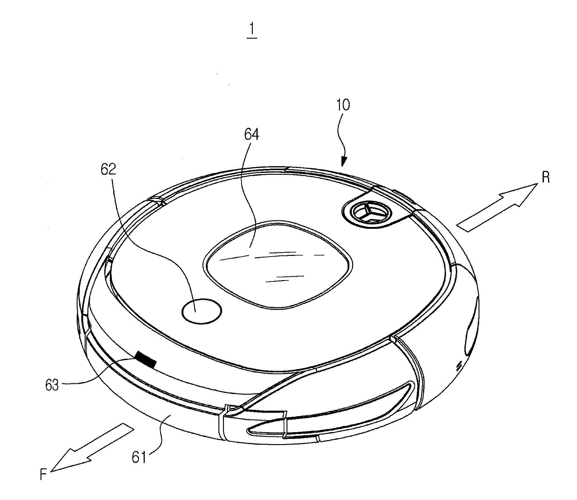
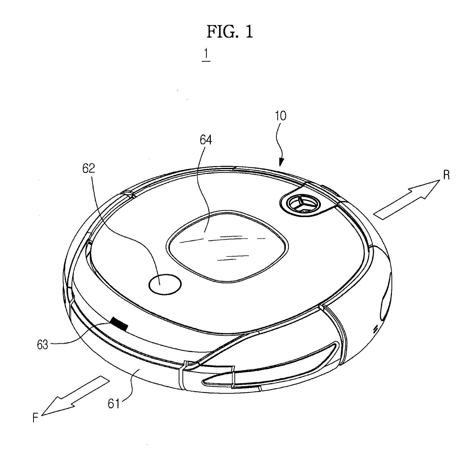
[0065]FIG. 1 is a view schematically illustrating an outer appearance of a robot cleaner according to an exemplary embodiment of the present disclosure.

[0066]Referring to FIG. 1, the robot cleaner, which is designated by reference numeral “1”, includes a body 10 to define an outer appearance of the robot cleaner 1.

[0067]Various sensors are mounted to the body 10, to sense an obstacle. The sensors may include a proximity sensor 61 and / or a vision sensor 62. For example, when the robot cleaner 1 travels in a random direction under the condition that there is no predetermined path, along which the robot cleaner 1 travels, that is, in a cleaning system having no map, the robot cleaner 1 may travel about a cleaning region and sense an obstacle, using the proximity sensor 61. On the other hand, when the robot cleaner 1 travels along a predetermined path, that is, in a cle...


PUM


Abstract

A robot cleaner includes a body to travel on a floor, an obstacle sensing unit to sense an obstacle approaching the body, an auxiliary cleaning unit mounted to a bottom of the body, to be extendable and retractable, and a control unit to control extension or retraction of the auxiliary cleaning unit when the obstacle is sensed. The control unit recognizes a zone of a charger and performs a control operation to prevent the auxiliary cleaning unit from extending in the charger zone.

Description

CROSS-REFERENCE TO RELATED APPLICATIONS[0001]This application claims the benefit of Korean Patent Application Nos. 10-2011-108221 and 10-2012-22470, respectively filed on Oct. 21, 2011 and Mar. 5, 2012 in the Korean Intellectual Property Office, the disclosures of which are incorporated herein by reference.BACKGROUND[0002]1. Field[0003]Embodiments of the present disclosure relate to a robot cleaner and a control method for the same, which are capable of automatically cleaning a region to be cleaned by removing dust or the like from a floor of the cleaning region while traveling about the cleaning region.[0004]2. Description of the Related Art[0005]A robot cleaner is a device for automatically cleaning a region to be cleaned by sucking foreign matter such as dust from a floor of the cleaning region while autonomously traveling about the cleaning region without user control. Such a robot cleaner not only includes a main brush to remove dust or the like accumulated on a region beneath ...

Claims


Application Information

Patent Timeline
25 Apr 2013
Publication
US20130098401A1
IPC
B08B1/00; A46B13/00
CPC
A47L11/33; A47L2201/04; A47L2201/022; A47L11/4055; A47L2201/02; A47L9/0488; G05D2109/10; G05D2105/10
Inventors
YOON, SANG SIK; KIM, BYUNG CHAN