

Pen head configuration structure for capacitive touch-screen stylus pen
- Summary
- Abstract
- Description
- Claims
- Application Information
AI Technical Summary
Benefits of technology
Problems solved by technology
Method used
Image

Examples
first embodiment
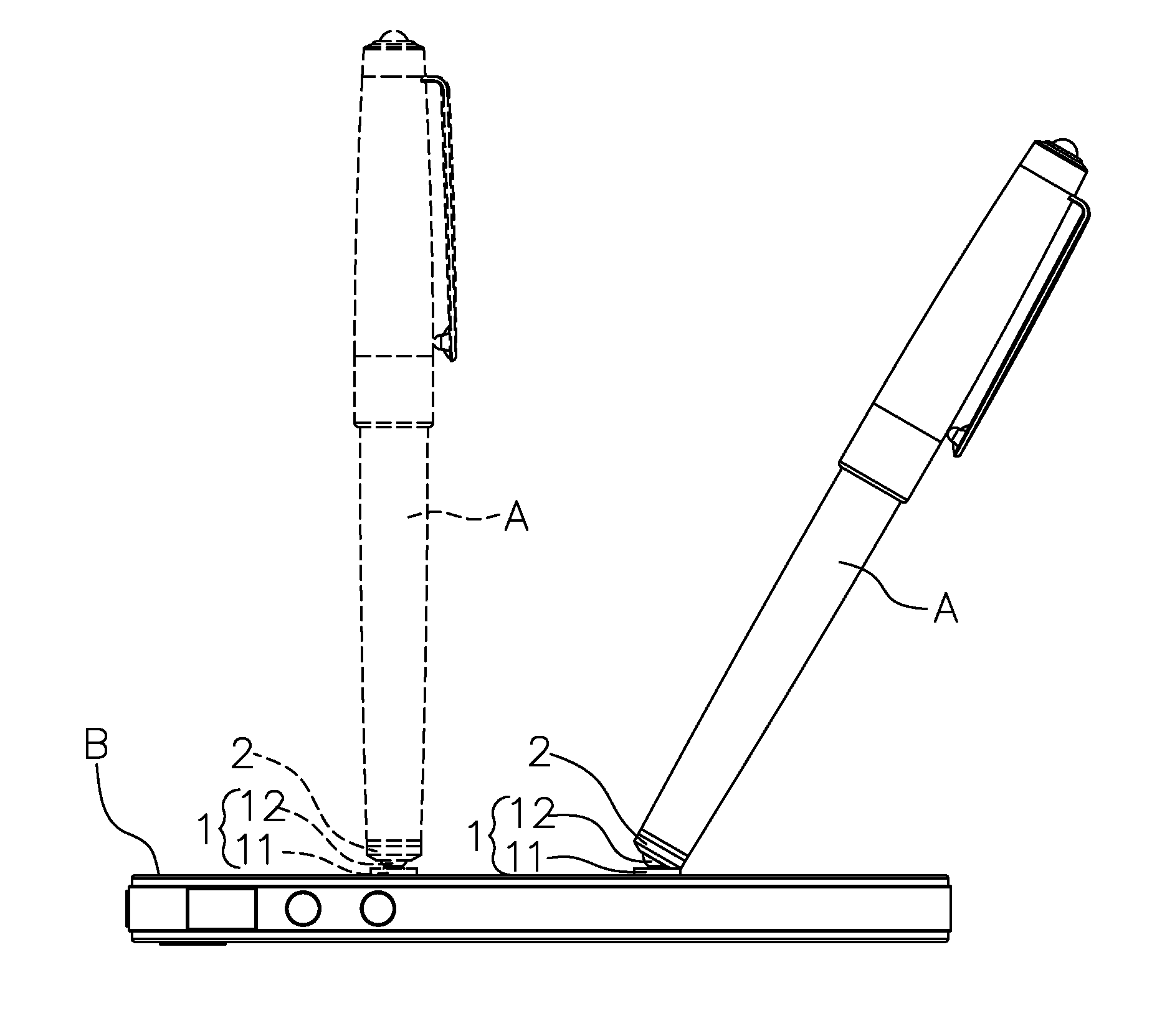
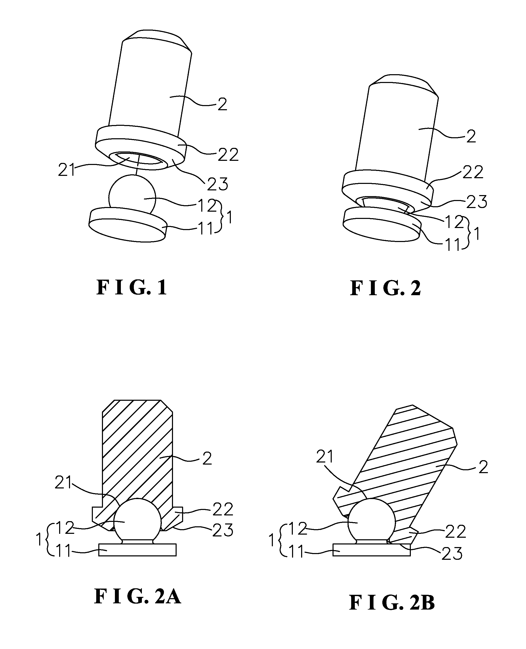
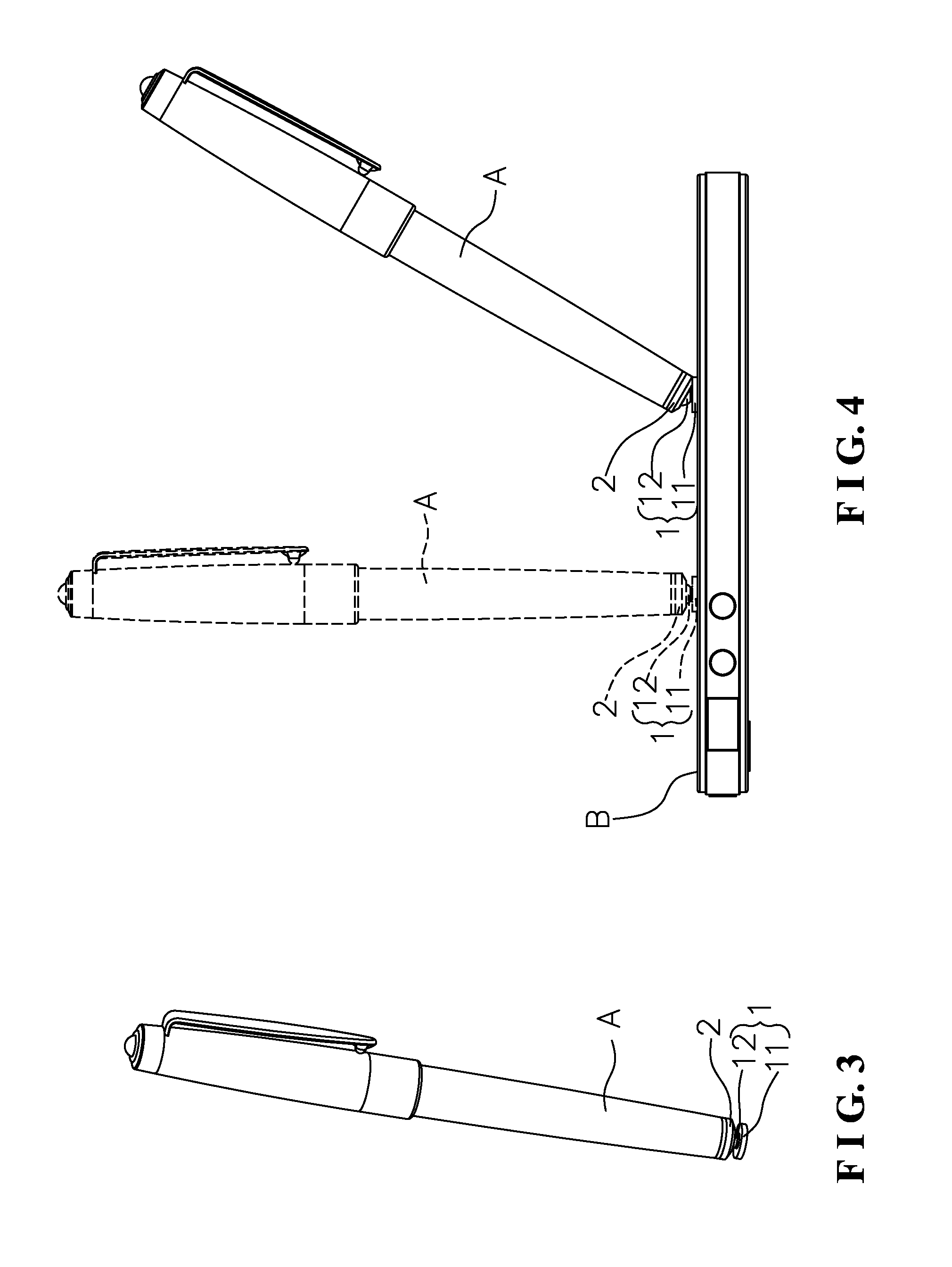
[0053]As shown in FIG. 1 to FIG. 4, in the present invention, the pen head 1 comprises a working portion 11 and a connecting portion 12. The working portion 11 is an end face made of a conductive material, namely, the working face of the stylus pen and the touchscreen. The connecting portion 12 is a spherical head disposed on top of the working portion 11. The spherical head is made of a conductive material or a hard conductive material. The support saddle 2 has a spherical socket 21 with a reduced opening at a lower end thereof to accommodate the upper part of the spherical head of the connecting portion 12. That is to say, the depth of the spherical socket 21 is greater than the radius of the spherical head of the connecting portion 12 and less than the diameter of the spherical head. The spherical head cooperates with the spherical socket 21 to form the universal joint. The support saddle 2 has a flange 22 at the lower end thereof. When the upper portion of the support saddle 2 i...
second embodiment
[0056]As shown in FIG. 5 to FIG. 8, in the present invention, the support saddle 4 comprises a lower pen head connecting portion 41 and an upper pen body connecting portion 42. The pen head connecting portion 41 is a spherical head. The pen body connecting portion 42 is a rod body which has a flange 43 at a lower end thereof. When the pen body connecting portion 42 of the support saddle 4 is inserted into the stylus pen, the flange 42 is flush with the lower end of the pen body to be an integral whole. The pen head 3 is a cylindrical seat made of a conductive material. The pen head 3 has a spherical head seat 31 at an upper portion thereof relative to the spherical head of the pen head connecting portion 41. The depth of the spherical head seat 31 is greater than the radius of the spherical head of the pen head connecting portion 41 and less than the diameter of the spherical head. The spherical head of the pen head connecting portion 41 cooperates with the spherical head seat 31 of...
third embodiment
[0058]As shown in FIG. 9 to FIG. 12, in the present invention, the pen head configuration structure for a capacitive touch-screen stylus pen comprises a pen head 5, a support saddle 6, a backing member 7 and a lock pin 8.
[0059]The pen head 5 is a spherical crown member made of a conductive material. The pen head 5 has a working end face 51 at a lower end face thereof to touch the touchscreen. The upper part of the pen head 5 is a spherical head 52. The spherical head 52 is formed with a taper seat 521 which is tapered from top to bottom. The spherical head 52 is formed with a sphere seat 522 near a middle part thereof at the lower part of the taper seat 521. The depth of the sphere seat 522 is greater than the radius of a sphere 71 of the backing member 7 and less than the diameter of the sphere 71. The backing member 7 and the pen head 5 form a universal connection relationship. The taper seat 521 is adapted for movement of the backing member 7. The support saddle 6 comprises a low...
PUM
 Abstract
Description
Claims
Application Information