Method and apparatus for determining the location of a femtocell

Active Publication Date: 2013-04-25
VIAVI SOLUTIONS UK
View PDF0 Cites 9 Cited by
  • Summary
  • Abstract
  • Description
  • Claims
  • Application Information

AI Technical Summary

Benefits of technology

[0016]Accordingly, the invention seeks to mitigate, alleviate or eliminate o

Problems solved by technology

However, the location of the

Method used


Image

  • Method and apparatus for determining the location of a femtocell
  • Method and apparatus for determining the location of a femtocell
  • Method and apparatus for determining the location of a femtocell

Examples


Embodiment Construction

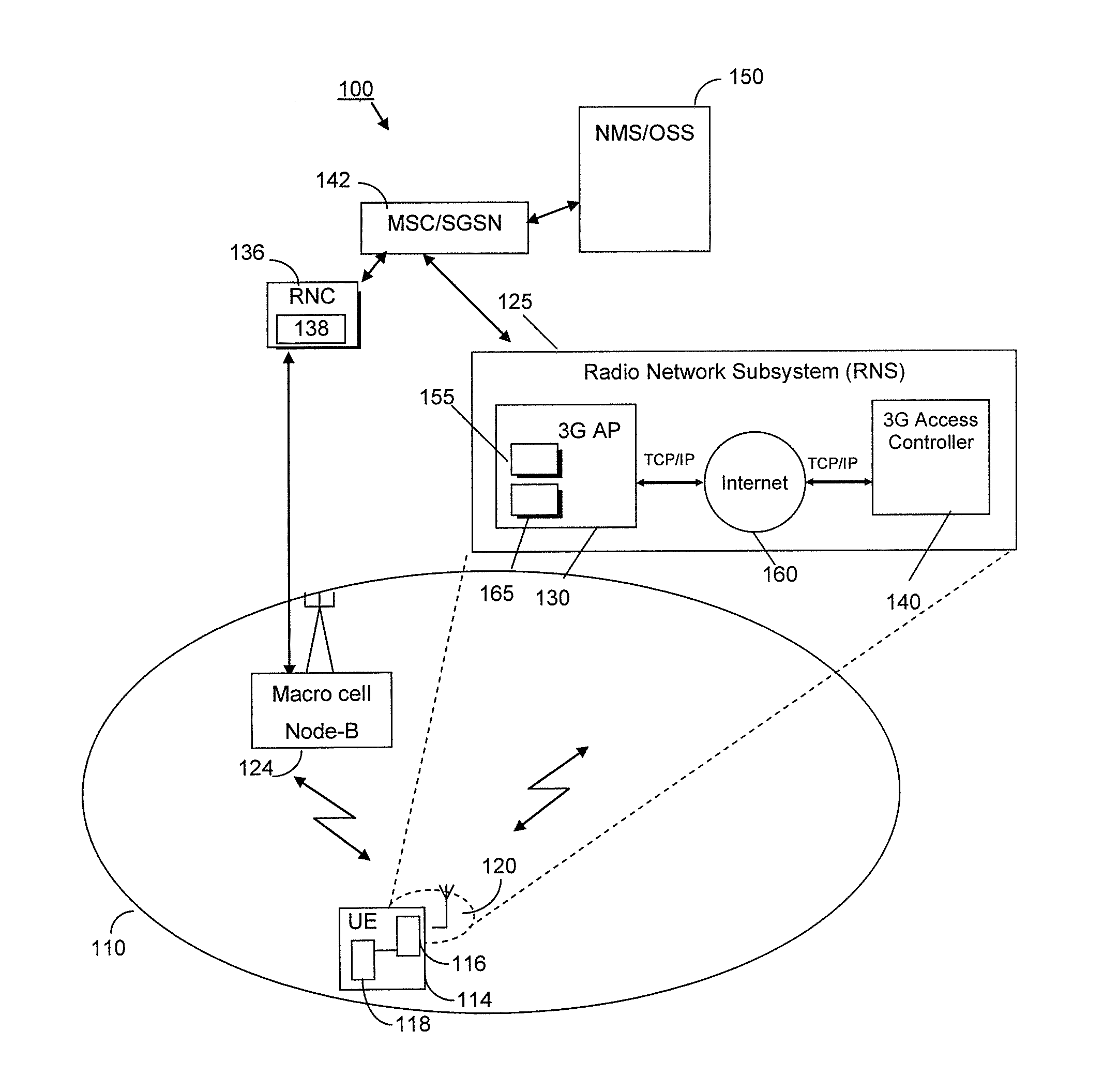
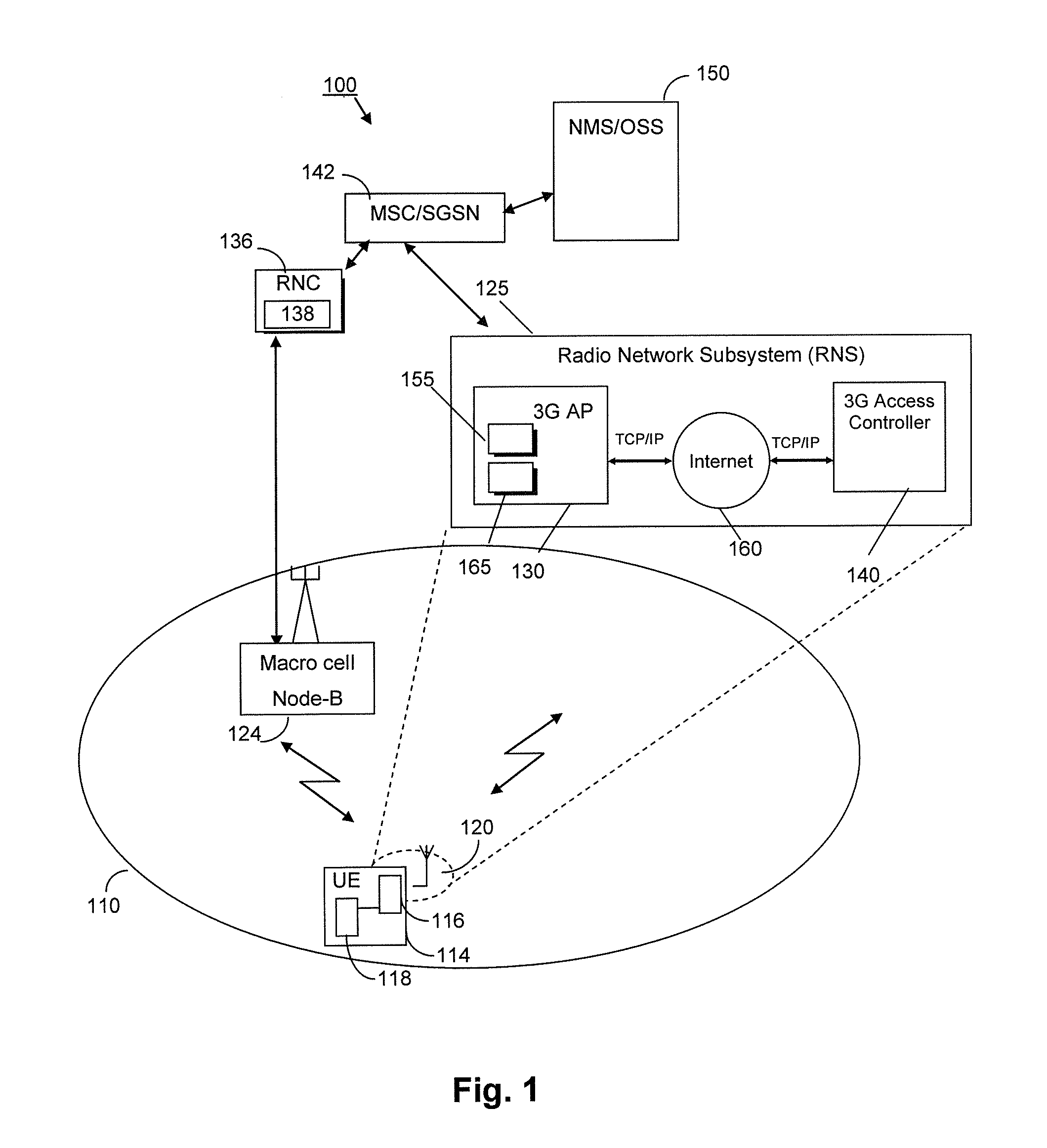
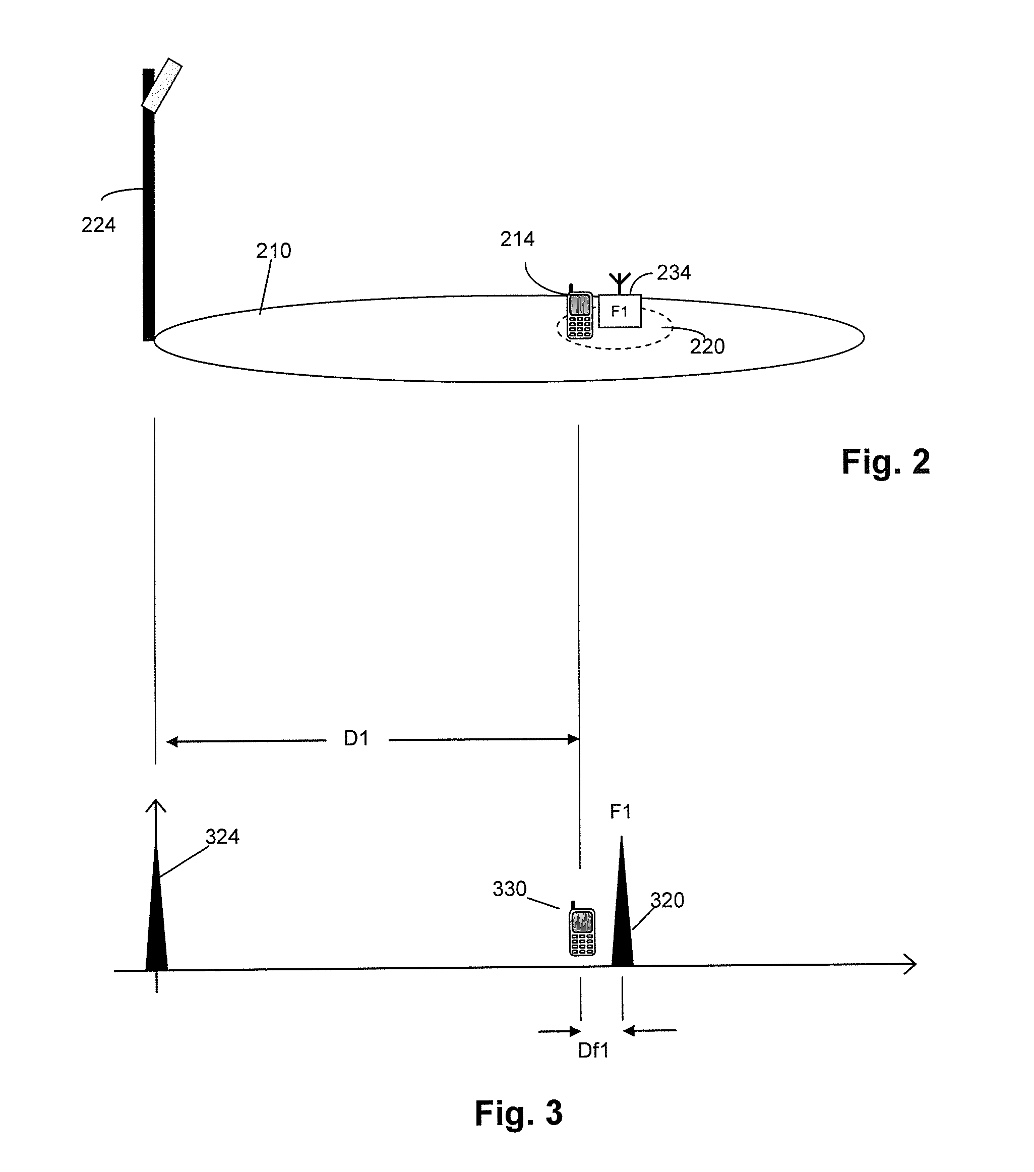
[0033]Examples of the invention will be described in terms of a method and apparatus for geolocating a femtocell of an asynchronous cellular wireless communication system. The figures showing the asynchronous cellular wireless communication system are generally designed as perspective views. This provides an illustration of the coverage area of the macro cells and femto cells, besides illustrating in schematic terms the hardware that provides that coverage.

[0034]The asynchronous cellular wireless communication system includes a plurality of macro cells and a plurality of wireless mobile communication units, and for example may be a Universal Mobile Telecommunications System (UMTS™). However, the inventive concept herein described may be implemented within asynchronous cellular communication networks adapted in accordance with alternative wireless communication technologies and standards.

[0035]Typically, femto and macro cells are considered to be part of a ‘network’ of the communicat...


PUM


Abstract

A system and method of determining the geographical location of a femtocell (640A) of an asynchronous cellular wireless communication system (600) are provided. Timing data is obtained from communication signals received by a first group of mobile communication units (450) from a femtocell (640A), and from at least two macro cells (410A, 420A, 670A). A difference (D12) in path distance from two macro cells to the femtocell (640A) is estimated using the timing data. A correction is made to remove timing offsets of the base stations of the macro cells. This provides an estimate of the geographical location of the femtocell (640A), when combined with either a similar estimate derived from signals received from a third macrocell, or an estimate derived from signal propagation data.

Description

FIELD OF THE INVENTION[0001]The field of the invention relates to a method and apparatus for determining the location of a femtocell. The femtocell may be within the footprint of a macro cell of a wireless communication network.BACKGROUND OF THE INVENTION[0002]Wireless communication systems, such as the 3rd Generation (3G) of mobile telephone standards and technology, are well known. An example of such 3G standards and technology is the Universal Mobile Telecommunications System (UMTS™), developed by the 3rd Generation Partnership Project (3GPP™) (www.3gpp.org).[0003]The 3rd generation of wireless communications has generally been developed to support macro-cell mobile phone communications. Such macro cells are relatively large. They use high power base stations to communicate with wireless communication units within a relatively large geographical coverage area. These base stations are called ‘NodeBs’, in 3GPP terminology. One base station may provide coverage over several square k...

Claims


Application Information

Patent Timeline
IPC IPC(8): H04W24/00
CPCH04W84/045H04W64/003G01S5/10G01S5/0278
Inventor FLANANGAN, MICHAEL JOSEPH
Owner VIAVI SOLUTIONS UK
Why Eureka
Try Eureka