Energy recovery ventilation control system

a technology of ventilation control system and energy recovery, which is applied in the direction of ventilation control system, space heating and heating apparatus, heating types, etc., can solve the problems of moisture build-up in and on the wheel

Active Publication Date: 2013-05-02
AIR DISTRIBUTION TECH IP LLC
View PDF11 Cites 18 Cited by
  • Summary
  • Abstract
  • Description
  • Claims
  • Application Information

AI Technical Summary

Problems solved by technology

One disadvantage of using a wheel is moisture build up in and on the wheel.

Method used


Image

  • Energy recovery ventilation control system
  • Energy recovery ventilation control system
  • Energy recovery ventilation control system

Examples


Embodiment Construction

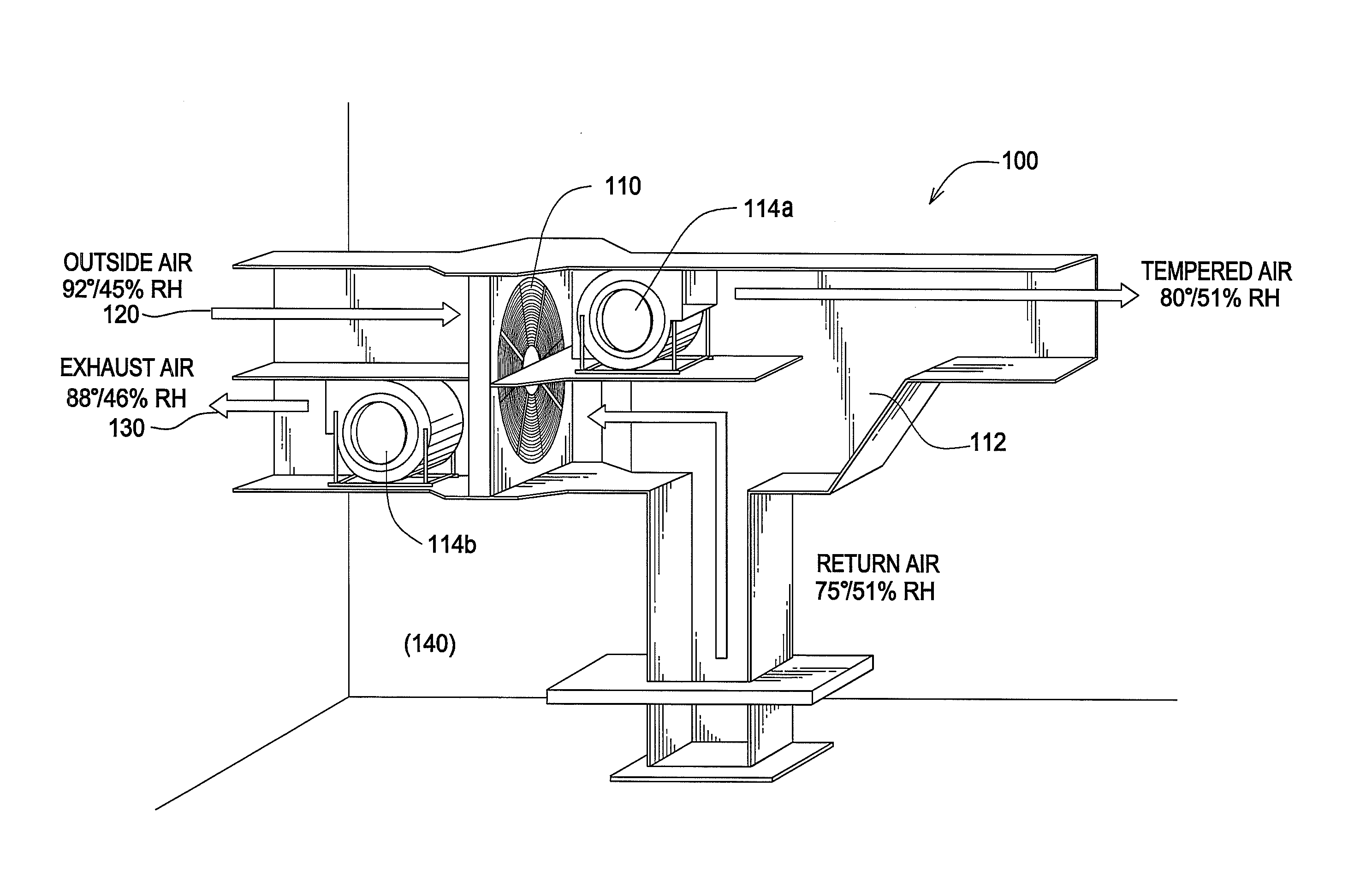
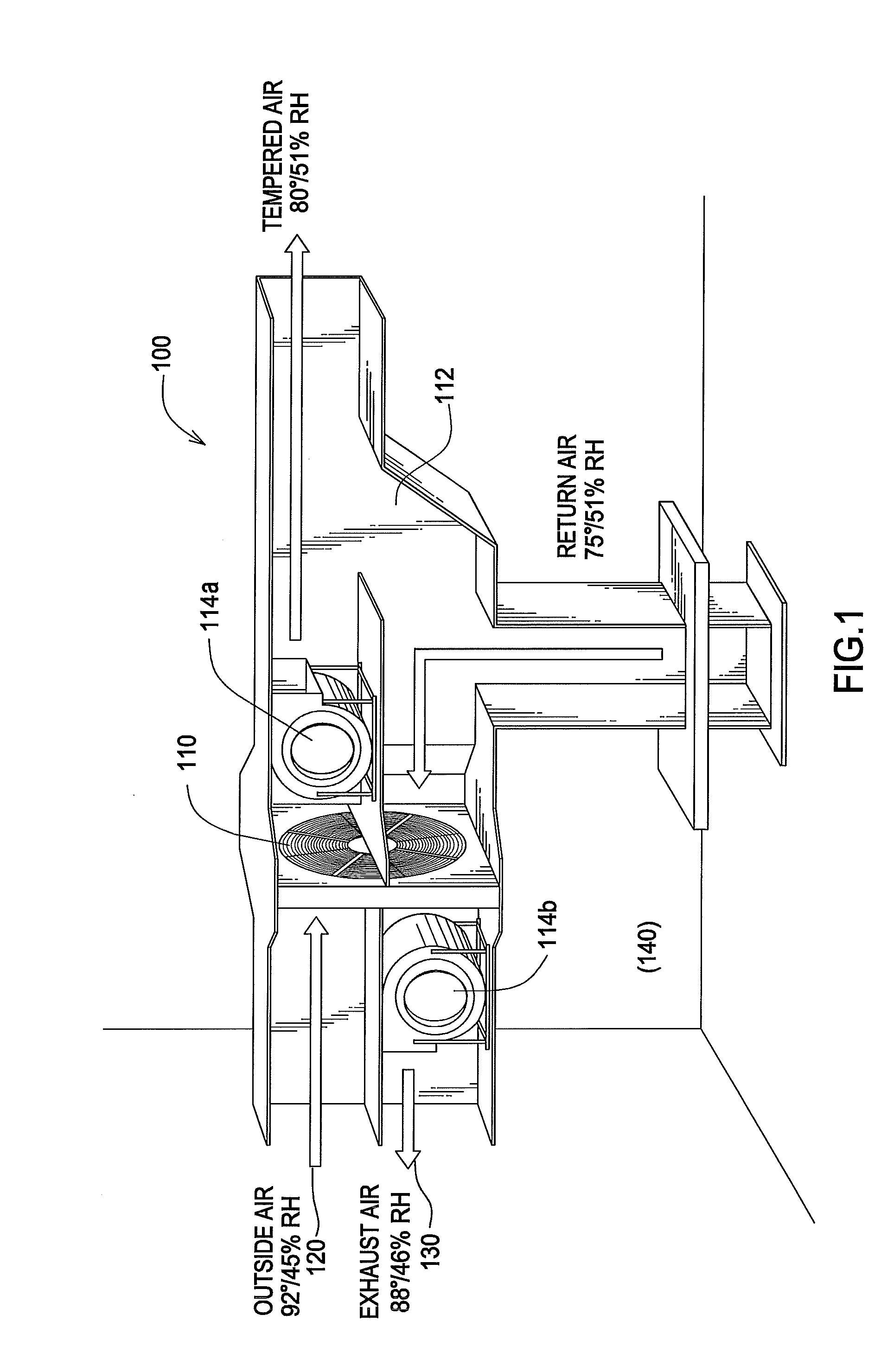
[0015]FIG. 1 shows a general ERV system 100. System 100 may be an air-to-air type heat exchanger. System 100 may include an energy recovery ventilation wheel, or thermal wheel, or enthalpy wheel (wheel) 110. As the wheel rotates between the ventilation 120 and exhaust air 130 streams it may pick up heat energy and release it into the colder air stream. In different seasons the inside or the outside air may have more heat or moisture or both and thereby more energy.

[0016]The system 100 in FIG. 1 may show an embodiment where the outside air 120 is warmer than the inside air 140. As can be seen, the conditioned inside air that is being exhausted 130 may be mixed with the incoming outside air 120, via a bypass opening 112 to lower the temperature and raise the relative humidity of the incoming outside air. A portion of the exhaust flow 130 may also pass thorough wheel 110 in addition to flowing through the bypass 112. Wheel 110 rotates to cool the incoming outside air. This helps reduce...


PUM


Abstract

A control system comprising a temperature sensor, an enthalpy sensor and a processor capable of receiving said temperature and enthalpy signals and further capable of controlling the operation of an energy recovery ventilation wheel based at least in part on said temperature and enthalpy signals.

Description

REFERENCE TO RELATED APPLICATIONS[0001]This non-provisional application claims priority from copending U.S. provisional application Ser. No. 61 / 554,040 filed Nov. 1, 2011BACKGROUND OF THE INVENTION[0002]This disclosure relates generally to air handling systems for buildings, more particularly to energy recovery ventilation systems, and specifically to a temperature and / or enthalpy control for an energy recovery wheel.[0003]The present disclosure is directed to systems and methods which control energy recovery ventilation (ERV) systems of buildings. ERV systems may be used to recover energy and lower utility expenses. Energy recovery wheels rotate between the incoming outdoor air and the exhaust air. As the wheel rotates, it transfers a percentage of the heat and moisture differential from one airstream to the other. The outdoor air is pre-conditioned reducing the capacity and energy needed from the mechanical HVAC system. According to guidelines, building environments require a spec...

Claims


Application Information

Patent Timeline
Patent Type & Authority Applications(United States)
IPC IPC(8): F28D19/00
CPCF28D19/042F24F2203/104F24F2011/0013F24F3/147F28D21/0014F24F2110/12F24F11/77F24F2110/22Y02B30/70F24F13/222
Inventor WILEY, JOSIAHLONGMAN, MICHAEL G.MOODY, SEAN ANDREW
Owner AIR DISTRIBUTION TECH IP LLC
Why Eureka
Try Eureka