
Event data recorder with low power consumption

a technology of event data and recorder, which is applied in the field of event data recorder, can solve the problems of limited parking mode, difficult or inability to start the car, and limited operation time of the prior art edr b>100/b>

Inactive Publication Date: 2013-05-02
PIXART IMAGING INC
View PDF6 Cites 11 Cited by
  • Summary
  • Abstract
  • Description
  • Claims
  • Application Information

AI Technical Summary

Benefits of technology

This patent describes an event data recorder with an image-recording module and a control module. The image-recording module can capture images and videos in two different modes: a video recording mode and a photograph mode. The control module can activate the image-capturing circuit to perform the photograph mode at specific times. The data recorder also includes a processing circuit that can detect specific events and generate a wakeup signal. The control module can then activate the image-capturing circuit to perform the video recording mode. The image-recording module can also receive a module clock signal and perform the image-capturing functions accordingly. This allows for flexibility and versatility in image and video recording capabilities. The event data recorder also includes a built-in power supply module and a power supply module that can receive external power or built-in power. The control module can decide to use the built-in power when the external power is not available. This makes the device more reliable and flexible in various situations.

Problems solved by technology

Therefore, the operational time of the prior art EDR 100 is limited in the parking mode.
The EDR 100 may fail to record events which occur after the automotive battery becomes flat, which also makes it difficult or unable to start the car.

Method used


Image

  • Event data recorder with low power consumption
  • Event data recorder with low power consumption
  • Event data recorder with low power consumption

Examples


Embodiment Construction

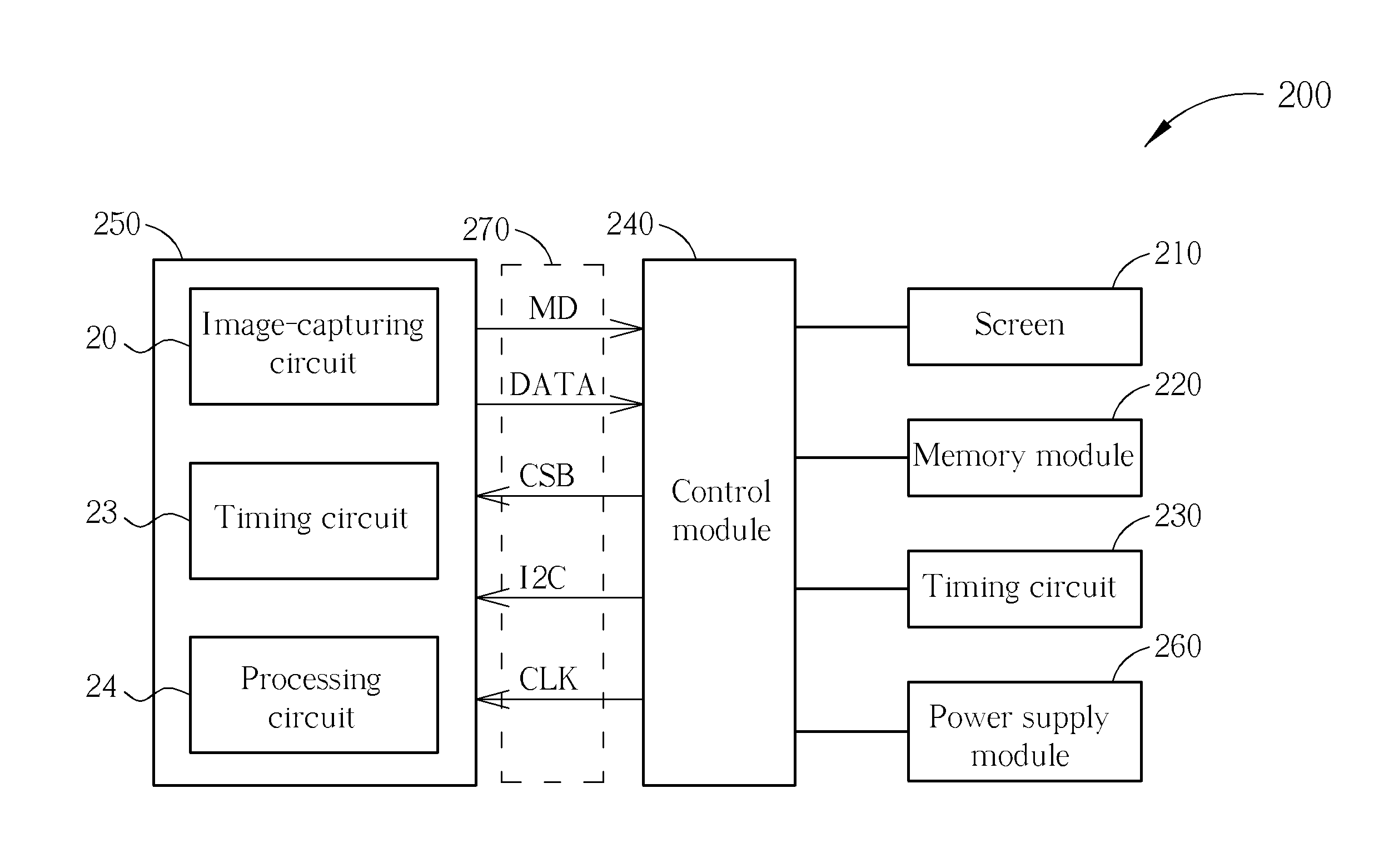
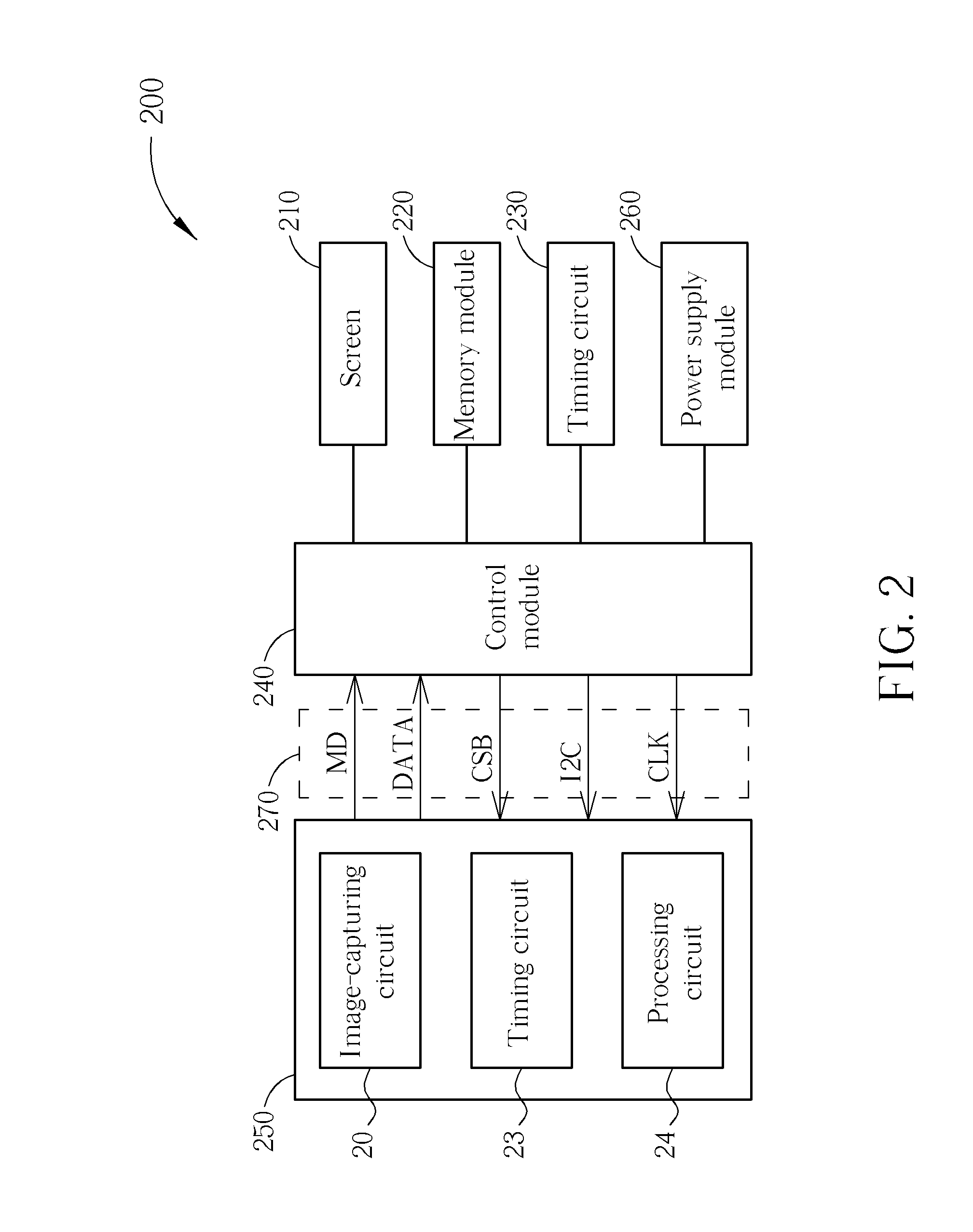
[0014]FIG. 2 is a functional diagram of an EDR 200 according to the present invention. The EDR 200 includes a screen 210, a memory module 220, a timing circuit 230, a control module 240, an image-recording module 250, a power supply module 260, and a transmitting interface 270. The screen 210 may be a liquid crystal display capable of displaying real-time images or previously recorded images. The memory module 220, which may include a buffer memory, a built-in memory / hard disc, or a module capable of communicating with an external memory / hard disc, is configured to store image data or the settings of the EDR 200. The timing circuit 130 may be a crystal oscillator configured to provide reference clock signals for operating the EDR 200. The control module 240 may be a back-end chip configured to control the operation of each device in the EDR 200. The image-recording module 250 may include one or multiple image-capturing circuits 20, a timing circuit 23, and a processing circuit 24.

[0...


PUM


Abstract

An event data recorder (EDR) is configured to operate in a driving mode and a parking mode. In the driving mode, the EDR is configured to perform high quality video recording using an image-capturing circuit. In the parking mode, the EDR is configured to periodically activate the image-capturing circuit for event detection and start to perform low quality video recording after detecting a specific event.

Description

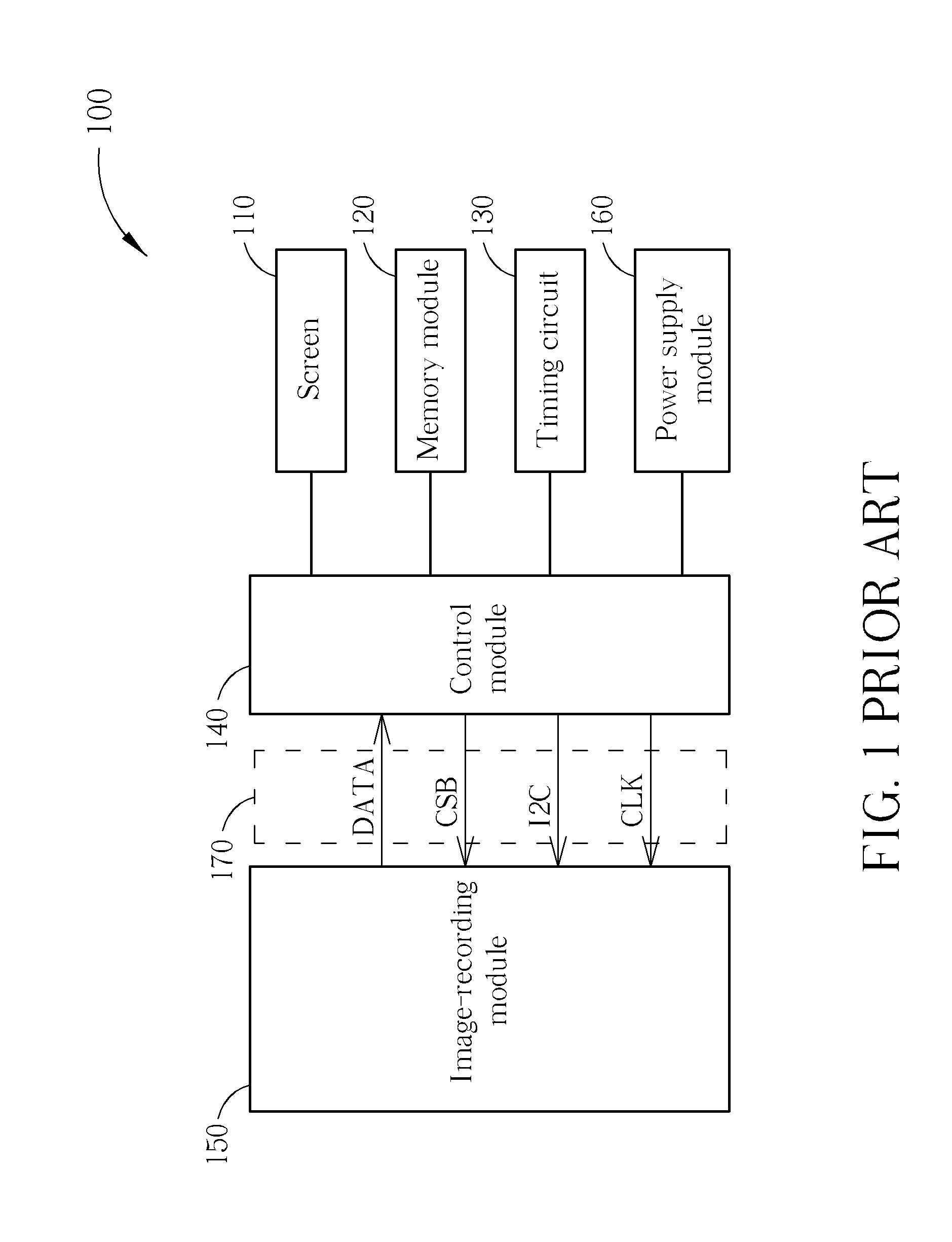
BACKGROUND OF THE INVENTION[0001]1. Field of the Invention[0002]The present invention is related to an event data recorder, and more particularly, to an event data recorder which reduces power consumption in the parking mode.[0003]2. Description of the Prior Art[0004]An event data recorder or EDR is a device installed in automobiles to record information related to vehicle, such as crashes, accidents or thefts. Police, crash investigators, and others can download the data from the EDR's memory to help them better understand what happened to the vehicle and how the safety systems performed, and in some cases, help establish culpability. An EDR normally provides two operational modes: the driving mode and the parking mode.[0005]FIG. 1 is a functional diagram of a prior art EDR 100. The EDR 100 includes a screen 110, a memory module 120, a timing circuit 130, a control module 140, an image-recording module 150, a power supply module 160, and a transmitting interface 170. The image-reco...

Claims


Application Information

Patent Timeline
IPC IPC(8): H04N5/76
CPCG07C5/0866H04N5/23241H04N2201/3253H04N5/772H04N5/225H04N23/65H04N23/00
Inventor HSU, EN-FENGKAO, MING-TSAN
Owner PIXART IMAGING INC
Learn More